


9
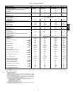
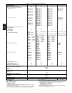
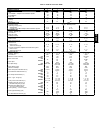
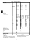
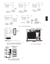
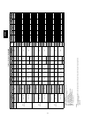
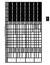
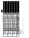
Table 1—Physical Data 48HJ
BASE UNIT 48HJ HJE/F/H/K/M/N004 HJD/E/F/G/H/K/L/M/N005 HJD/E/F/G/H/K/L/M/N006 HJD/E/F007
NOMINAL CAPACITY
3 4 5 6
OPERATING WEIGHT (lb)
Unit
530 540 560 635
Humidi-MiZer Adaptive Dehumidification System
15 23 25 29
EconoMi$er IV
50 50 50 50
Roof Cur b
115 115 115 115
COMPRESSOR
Scroll
Quantity
1 1 1 1
Oil (oz)
42 53 50 60
REFRIGERANT TYPE
R-22
Expansion Device
Acutrol Metering Devi ce
Operating Charge (lb-oz)
StandardU nit
5-8 10-2 10-0 12- 8
Unit With Humidi-Mizer Adaptive Dehumidification System
12-5 18-8 20-5 23-14
CONDENSER FAN
Propeller
Quantity...Diameter (in.)
1...22 1...22 1...22 1...22
Nominal C f m
3500 3500 4100 4100
Motor Hp...Rpm
1
/
4
...825
1
/
4
...825
1
/
4
...1100
1
/
4
...1100
Watts Input (Total)
180 180 320 320
CONDENSER COIL
Enhanced Copper Tubes, Aluminum Lanced Fins
Rows...Fins/in.
1...17 2...17 2...17 2...17
Total Face Area (sq ft)
14.6 16.5 16.5 21.3
EVAPORATOR COIL
Enhanced Copper Tubes, Aluminum Double-Wavy Fins
StandardU nit
Rows...Fins/in.
2...15 2...15 4...15 4...15
Total Face Area (sq ft)
5.5 5.5 5.5 7.3
Unit with Humidi-Mizer Adaptive Dehumidification System
Rows...Fins/in.
1...17 2...17 2...17 2...17
Total Face Area (sq ft)
3.9 3.9 3.9 5.2
EVAPORATOR FAN
Centrifugal Type, Belt Drive
Quantity...Size (in.)
1...10 x 10 1...10 x 10 1...10 x 10 1...10 x 10
Nominal C f m
1200 1600 2000 2400
Maximum Continuous Bhp Std
1.20
1.20 1.30/2.40* 2.40
Hi-Static
2.40
2.40 2.90 2.90
Motor R PM Std
1620
1620 1725 1725
Hi-Static
1725
1725 1725 1725
Motor Frame Size Std
48
48 48/ 56* 56
Hi-Static
56
56 56 56
Fan Rpm Range Std
680-1044
770-1185 1035-1460 1119-1585
Hi-Static
1075-1455
1075-1455 1300-1685 1300-1685
Motor Bearing Type
Ball Ball Ball Ball
Maximum Fan Rpm
2100 2100 2100 2100
Motor Pulley Pitch Diameter A/B (in.)
Std
1.9/2.9
1.9/2.0 2.4/ 3.4 2.4/3.4
Hi-Static
2.8/3.8
2.8/3.8 3.4/ 4.4 3.4/3.4
Nominal Motor Shaft Diameter (in.) Std
1/
2
1
/
2
5
/
8
5
/
8
Hi-Static
5
/
8
5
/
8
5
/
8
7
/
8
Fan Pull ey Pitch Diameter (in.) Std
4.5
4.0 4.0 4.0
Hi-Static
4.5
4.0 4.5 4.5
Belt — Type...Length (in.) Std
1...A...36
1...A...36 1....4...40 1...A...38
Hi-Static
1...A...39
1...A...39 1...A...40 1...A...40
Pulley Center Line Distance (in.)
10.0-12.4 10.0-12.4 14.7-15.5 14.7-15.5
Speed Change per Full Turn of
Movable Pulley Flange (rpm)
Std
65
70 75 95
Hi-Static
65
65 60 60
Movable Pulley Maximum Full
Turns from ClosedPosition
Std
5
5 6 5
Hi-Static
6
6 5 5
Factory Setting— Full Turns Open Std
3
3 3 3
Hi-Static
3
1
/
2
3
1
/
2
3
1
/
2
3
1
/
2
Factory Speed Setting (rpm) Std
826
936 1248 1305
Hi-Static
1233
1233 1396 1396
Fan Shaft Diameter atPull ey (in.)
5
/
8
5
/
8
5
/
8
5
/
8
LEGEND
Bhp — Brake Horsepower
*Single phase/three phase.
†Indicatesautomaticreset.
**60,000 and 72,000 Btuh heat input units have 2 burners. 90,000 a nd 120,000
Btuh heat input units have 3 burners. 115,000 Btuh heat input units and 150,000
Btuh Heat input units have 3 burners.
††AnLP kitis available asan accessory.Kit maybe usedat elevations ashighas 2000
ft. If an LP kit is used withLow NOx units, the Low NOx baffle must be removed and
the units will no longer be classified as Low NOx units.
ll Three-phase standard models have heating inputs as shown. Single-phase stan-
dard models have one-stage heating with heating input values as follows:
HJD005-006,HJE004— 72,000B tuh
HJE005-006,HJF004— 115,000 Btuh
HJF005-006 —150,000 Btuh
***California compliantthree-phase models.
†††California SCAQMD compliant low NO
x
modelshave combustion products that are
controlledto 40nanogramsperjouleor less.
48HE,HJ