


60
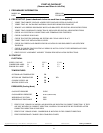
3. Set DCV maximum position potentiometer to previous
setting.
4. Set minimum position, DCV set point, and exhaust
potentiometers to previous settings.
5. Remove 620-ohm resistor from terminals S
R
and +.
6. Remove 1.2 kilo-ohm checkout resistor from terminals S
O
and +. If used, reconnect sensor from terminals S
O
and +.
7. Remove jumper from TR to N.
8. Remove jumper from TR to 1.
9. Remove 5.6 kilo-ohm resistor from T and T1. Reconnect
wires at T and T1.
10. Remove jumper from P to P1. Reconnect device at P and
P1.
11. Apply power (24 vac) to terminals TR and TR1.
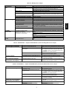
Table41—LEDErrorCodeServiceAnalysis
SYMPTOM CAUSE REMEDY
Hardware Failure.
(LED OFF)
Loss of power to control module (IGC). Check 5 amp fuse on IGC, power to unit, 24-v circuit breaker, and
transformer. Units without a 24-v circuit breaker have an internal
overload in the 24-v transformer. If the overload trips, allow
10 minutes for automatic reset.
Fan ON/OFF Delay Modified
(LED/FLASH)
High limit switch opens during heat
exchanger warm-up period before fan-on
delay expires.
Limit switch opens within three minutes
after blower-off delay timing in Heating
mode.
Ensure unit is fired on rate and temperature rise is correct.
Ensure units’ external static pressure is w ithin application guide-
lines.
Limit Switch Fault.
(LED 2 Flashes)
High temperature limit switch is open. Check the operation of t he indoor (evaporator) fan motor.
Ensure that the supply-air temperature rise is in accordance with
the range on the unit nameplate.
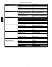
Flame Sense Fault.
(LED 3 Flashes)
The IGC sensed flame that should not be
present.
Reset unit. If problem persists, replace control board.
4ConsecutiveLimit
Switch Faults.
(LED 4 Flashes)
Inadequate airflow to unit. Check operation of indoor (evaporator) fan motor and that supply-air
tem perat ure ri s e agre es w i th r ange on uni t n ame plat e i nfor mat i on.
Ignition Lockout.
(LED 5 Flashes)
Unit unsuccessfully attempted ignition for
15 minutes.
Check ignitor and flame sensor electrode spacing, gaps, etc.
Ensure that flame sense and ignition wires are properly
terminated. Verify that unit is obtaining proper amount of gas.
Induced-Draft Motor Fault.
(LED 6 Flashes)
IGC does not sense that induced-draft
motor is operating.
Check for proper voltage. If motor is operating, check the
speed sensor plug/IGC Terminal J2 connection. Proper
connection: PIN 1— White, PIN 2 — Red, PIN 3 — Black.
Rollout Switch Fault.
(LED 7 Flashes)
Rollout switch has opened. Rollout switch will automatically reset, but IGC will continue to
lock out unit. Check gas valve operation. Ensure that induced-
draft blower w heel is properly s ecured to motor shaft.
Reset unit at unit disconnect.
Internal Control Fault.
(LED 8 Flashes)
Microprocessor has sensed an error in the
software or hardware.
If error code is not cleared by resetting unit power, replace the IGC.
Temporary Software
Lockout
(LED 9 Flashes)
Electrical interference is impeding the IGC
software.
Reset 24-v to control board or turn thermostat off and then on. Fault
will automatically reset itself in one hour.
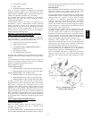
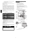
COMPONENT DAMAGE HAZARD
Failure to follow this caution may result in component
damage.
If the IGC must be replaced, be sure to ground yourself to
dissipate any electrical charge that may be present before
handling new control board. The IGC is sensitive to static
electricity and may be damaged if the necessary precautions
are not taken.
CAUTION
!
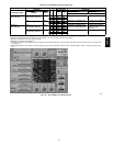
IMPORTANT: Refer to heating troubleshooting for additional
heating section troubleshooting information.
LEGEND
IGC --- Integrated Gas Unit Controller
LED --- Light ---Emitting Diode
48HE,HJ