


22
1. Use a 4-conductor, 18 or 20 AWG cable to connect the
enthalpy control to the PremierLink controller and
power transformer.
2. Connect the following 4 wires from the wire harness
located in rooftop unit to the enthalpy controller:
a. Connect the BRN wire to the 24 vac terminal (TR1) on
enthalpy control and to pin 1 on 12-pin harness.
b. Connect the RED wire to the 24 vacGND terminal (TR)
on enthalpy sensor and to pin 4 on 12-pin harness.
c. Connect the GRAY/ORN wire to J4-2 on PremierLink
controller and to terminal (3) on enthalpy sensor.
d. Connect the GRAY/RED wire to J4-1 on PremierLink
controller and to terminal (2) on enthalpy sensor.
NOTE: If installing i n a Carrier rooftop, use the two gray wires
provided from the control section to the economizer to connect
PremierLinkcontrollertoterminals2and3onenthalpysensor.
Return Air Enthalphy Sensor
Mount the return-air enthalpy sensor (HH57AC078) in the
return-air duct. The return air sensor is wired to the enthalpy
controller (HH57AC077). The outdoor enthalpy changeover set
point is set at the controller.
LED
A
B
C
D
TR TR1
SO
SR
2
3
1
+
+
BRN
RED
GRAY/ORN
GRAY/RED
WIRE HARNESS
IN UNIT
BLK
RED
S
+
(RETURNAIR
ENTHALPY
SENSOR)
S
+
(OUTDOOR
AIR
ENTHALPY
SENSOR)
ENTHALPY CONTROLLER
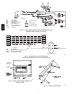
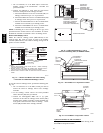
NOTES:
1. Remove factory-installed jumper across SR and + before connecting
wires from return air sensor.
2. Switches shown in high outdoor air enthalpy state. Terminals 2 and 3
close on low outdoor air enthalpy relative to indoor air enthalpy.
3. Remove sensor mounted on back of control and locate in outside air-
stream.
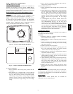
C06019
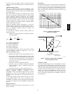
Fig. 27 --- Outdoor and Return Air Sensor Wiring
Connections for Differential Enthalpy Control
To wire the return air enthalpy sensor, perform the following (See
Fig. 27):
1. Use a 2--conductor, 18 or 20 AWG, twisted pair cable to
connect the return air enthalpy sensor to the enthalpy
controller.
2. At the enthalpy control remove the factory-installed
resistor from the (SR) and (+) terminals.
3. Connect the field-supplied RED wire to (+) spade
connector on the return air enthalpy sensor and the (SR+)
terminal on the enthalpy controller. Connect the BLK wire
to (S) spade connector on the return air enthalpy sensor
and the (SR) terminal on the enthalpy controller.
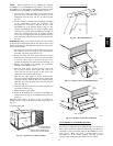
BRACKET
+
C7400A1004
HH57AC077
ENTHALPY
CONTROL AND
OUTDOOR AIR
ENTHALPY SENSOR
HH57AC078 ENTHALPY
SENSOR (USED WITH
ENTHALPY CONTROL
FOR DIFFERENTIAL
ENTHALPY OPERATION)
MOUNTING PLATE
C06020
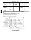
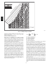
Fig. 28 --- Differential Enthalpy Control,
Sensor and Mounting Plate (33AMKITENT006)
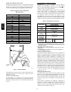
ECONOMI$ER IV
CONTROLLER
OUTSIDE AIR
TEMPERATURE SENSOR
LOW AMBIENT
SENSOR
A
CTUATOR
WIRING
HARNESS
C06021
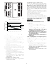
Fig. 29 --- EconoMi$er IV Component Locations
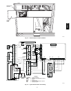
ECONOMI$ER2
PLUG
BAROMETRIC
RELIEF
DAMPER
OUTDOOR
AIR HOOD
HOOD
SHIPPING
BRACKET
GEAR DRIVEN
DAMPER
C06022
Fig. 30 --- EconoMi$er2 Component Locations
optional economi$er IV and
economi$er2
See Fig. 29 f or EconoMi $e r IV com ponent l ocations. See Fig. 30 f or
EconoM i$er2 com pone nt locations.
48HE,HJ