


52
Step 7 —Loss--of--Charge Switch
The loss-of-charge switch contains a Schrader core depressor, and
is located on the compressor liquid line. This switch opens at 7
psig and closes at 22 psig. No adjustments are necessary.
Step 8 —Fr eeze--Stat
The freeze-stat is a bimetal temperature-sensing switch t hat is
located on the “hair -pin” end of the evaporator coil. The switch
protects the evaporator coil from freeze-up due to lack of airflow.
The switch opens at 30_F and closes at 45_F. No adjustments are
necessary.
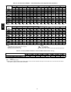
Step 9 —Refrigerant Charge
Amount of refrigerant charge is listed on unit nameplate (also
refer to Table 1). Refer to HVAC Servicing Procedures literature
available at your local distributor and the following procedures.
Unit panels must be in place when unit is operating during
charging procedure. Unit must operate a minimum of 10 minutes
before checking or adjusting refrigerant charge.
An accurate superheat, thermocouple-type or thermistor-type
thermometer, and a gauge manifold are required when using the
superheat charging method for evaluating the unit charge. Do not
use mercury or small dial-type thermometers because they are not
adequate for this type of measurement.
No
charge
Use standard evacuating techniques. After evacuating system to
500 microns, weigh in the specified amount of refrigerant. (Refer
to Table 1 or 2 and unit information plate.)
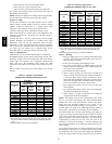
Low charge
cooling
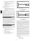
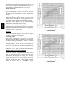
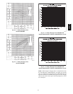
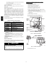
Using Cooling Charging Charts, Fig. 60--63, vary refrigerant
until the conditions of the charts are met. Note the char ging charts
are different from type normally used. Charts are based on
charging the units to the correct superheat for the various
operating conditions. Accurate pressure gage and temperature
sensing device are required. Connect the pressure gauge to the
service port on the suction line. Mount the temperature sensing
device on the suction line and insulate it so that outdoor ambient
temperature does not affect the reading. Indoor-air cfm must be
within the normal operating range of the unit.
HUMIDI--MIZER
SYSTEM CHARGING
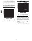
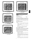
The system char ge for units with the Humidi-MiZer adaptive
dehumidification system is greater than that of the standard unit
alone. The charge for units with this option is indicated on the
unit nameplate drawing. Also refer to Fig. 64-67. To charge
systems using the Humidi-MiZer adaptive dehumidification
system, fully evacuate, recover, and recharge the system to the
nameplate specified char ge level. To check or adjust refrigerant
charge on systems using the Humidi-MiZer adaptive
dehumidification system, charge per Fig. 64-67.
C06139
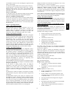
Fig. 60 --- Cooling Charging Chart,
Standard 48HJ004
C06140
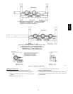
Fig. 61 --- Cooling Charging Chart,
Standard 48HJ005
48HE,HJ