


45
PRE-START-UP
FIRE, EXPLOSION, ELECTRICAL SHOCK HAZARD
Failure to follow this warning could re sult in personal
injury, dea th and/or property dama ge:
1. Follow r ecognized sa f ety practi ce s and wear protective
goggles w hen checking or servicing a refrigerant system .
2. D o not operate the com press or or p rovide a ny electric
powe r to the unit unle ss the compr essor termi nal cover is
in place and secured.
3. Do not remove the compr essor termi nal cover until al l
electrica l sour ce s a re disconne cted a nd t agge d wit h lockout
tags.
4. Rel ieve all pr essure from the s ystem be fore t ouching or
disturbing anyt hing insi de the te rminal box if a
refrigerant l eak i s sus pected a round t he compr es sor
terminals. Use accepted methods to recover the
refrigerant.
5. Never attempt to repair a soldered connection while the
refrigerant syste m is under pressure.
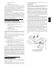
6. Do not use a torch t o re m ove any component. The
system cont ains oil and refrigera nt unde r pressure. To
remove a component, wear protective goggles and proceed
as follows:
a. Shut off electrical power to the unit and tag
disconnect.
b. Recover refrigerant to relieve all pressure
from the system using both high-pressure
and low-pressure ports.
c. Cut component connection tubing with a
tubing cutter, and remove the component
from the unit.
d. Carefully unsweat the remaining tubing
stubs when necessary. Oil can ignite when
exposed to a torch flame.
!
WARNING
Proceed as follows to inspect and prepare the unit for initial
start-up:
1. Remove all access panels.
2. Read and follow instructions on all WARNING,
CAUTION, and INFORMATION labels attached to, or
shipped with, unit.
3. Make the following inspections:
a. Inspect for shipping and handling damages such as
broken lines, loose parts, or disconnected wires, etc.
b. Inspectforoilatallrefrigeranttubingconnectionsandon
unit base. Detecting oil generally indicates a refrigerant
leak. Leak-test all refrigerant tubing connections using
electronic leak detector, halide torch, or liquid-soap
solution.
c. Inspect all field-wiring and factory-wiring connections.
Besurethatconnectionsarecompletedandtight.Besure
that wires are not in contact with refrigerant tubing or
sharp edges.
d. Inspect coil fins. If damaged during shipping and
handling, carefully straighten fins with a fin comb.
4. Verify the following conditions:
a. Make sure that condenser-fan blade are correctly
positionedinfanorifice.SeeCondenser-FanAdjustment
section for more details.
b. Make sure that air filter(s) is in place.
c. Make sure that condensate drain trap is filled with water
to ensure proper drainage.
d. Make sure that all tools and miscellaneous loose parts
have been removed.
START-UP
Step 1 —Unit Preparation
Make sure that the unit has been installed in accordance with
installation instructions and applicable codes.
Step 2 —Gas Piping
Check gas piping for leaks.
ELECTRICAL SHOCK HAZARD
Failure to follow this warning could cause personal
injury or death.
Disc onnect gas piping from unit when leak te s ting at
pressure greater than
1
/
2
psig. Pressures greater than
1
/
2
psig will cause gas valve damage resulting in hazardous
condition. If ga s va lve is s ubjected to press ure grea t er than
1
/
2
psig, it must be replaced before use. When pressure
testing field- supplied gas piping at pressures of
1
/
2
psig
or less, a unit connected to such pipi ng m ust be isol at ed by
ma nually closing the gas valve.
!
WARNING
Step 3 —Return--Air Filters
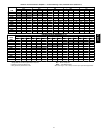
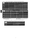
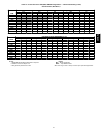
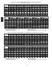
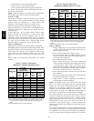
Make sure the correct filters are installed in the unit (See Table 1
or 2). Do not operate the unit without return-air filters.
Step 4 —Outdoor--Air Inlet Scr eens
Outdoor-air inlet screen(s) must be in place before operating the
unit.
Step 5 —Compressor Mounting
Compressors are internally spring mounted. Do not loosen or
remove the compressor holddown bolts.
Step 6 —Internal W iring
Check all electrical connections in unit control boxes; tighten
them as required.
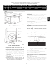
Step 7 —Refrigerant Service Ports
Each unit system has 4 Schrader--type service ports: one on the
suction line, one on the liquid line, and 2 on the compressor
discharge line. Be sure that caps on the ports are tight. Two
additional Schrader valves are located under the high--pressure
and low--pressure switches, respectively.
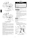
Step 8 —High Flow Refrigerant Valves
Two high flow valves are located on the hot gas tube coming out
of the compressor and the suction tube going into the compressor.
Larg e black plastic caps identify these valves. These valves have
O--rings inside which screw the cap onto a brass body to prevent
leaks. No field access to these valves is available a t this time.
Ensure the plastic caps r emain on the valves and are tight or the
possibility of refrigerant leakage could occur .
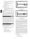
Step 9 —Compressor Rotation
On 3-phase units be certain that the compressor is rotating in the
proper direction. To determine whether or not compressor is
rotating in the proper direction:
1. Connect the service gauges to suction and discharge
pressure fittings.
2. Energize the compressor.
3. The suction pressure should drop and the discharge
pressure should rise, as is normal on any start-up.
If the suction pressure does not drop and the discharge pressure
does not rise to normal levels:
1. Note that the indoor fan (006 and 007 three-phase units
only) is probably also rotating in the wrong direction.
48HE,HJ