


55
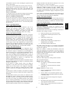
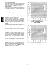
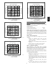
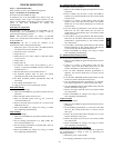
48HE -- 2 TON CHARGING CHART
65.0
70.0
75.0
80.0
85.0
90.0
95.0
100.0
105.0
42 52 62 72
SuctionLineTemp(degF)
SuctionLinePressure(psig)
448.0
498.0
548.0
598.0
648.0
698.0
5.5 10.5 15.5 20.5 25.5
SuctionLineT emperature (degC)
SuctionLinePressure(kpa)
FC
125 52
115 46
105 41
95 35
85 29
75 24
C06148
Fig. 68 --- Cooling Charging Chart,
Standard 48HE003
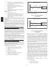
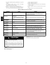
48HE -- 3TON CHARGINGCHART
65.0
75.0
85.0
95.0
43 48 53 58 63 68 73 78
SuctionLineTemp(degF)
SuctionLinePressure(psig)
448.2
498.2
548.2
598.2
648.2
6.1 11.1 16.1 21.1
SuctionLineTemperature(degC)
SuctionLinePressure(kpa)
FC
115 46
105 41
95 35
85 29
75 24
C06149
Fig. 69 --- Cooling Charging Chart,
Standard 48HE004
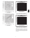
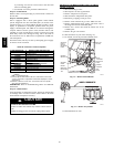
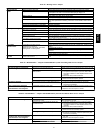
48HE-- 4TONCHARGINGCHART
67.0
77.0
87.0
97.0
42 47 52 57 62 67 72 77
SuctionLineTemp(degF)
SuctionLinePressure(psig)
492.0
542.0
592.0
642.0
692.0
5.6 10.6 15.6 20.6 25.6
SuctionLineTemperature(degC)
SuctionLinePressure(kpa)
FC
115 46
105 41
95 35
85 29
75 24
C06150
Fig. 70 --- Cooling Charging Chart,
Standard 48HE005
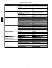
48HE -- 5 TON CHARGING CHART
55.0
65.0
75.0
85.0
95.0
105.0
115.0
42 47 52 57 62 67 72 77
SuctionLineTemp(degF)
SuctionLinePressure(psig)
310.0
410.0
510.0
610.0
710.0
810.0
0.0 5.0 10.0 15.0 20.0 25.0
SuctionLineT emperature (degC)
SuctionLinePressure(kpa)
FC
115 46
105 41
95 35
85 29
75 24
C06151
Fig. 71 --- Cooling Charging Chart,
Standard 48HE006
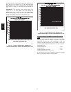
TO USE COOLING CHARGING CHARTS, UNITS
WITH
HUMIDI--MIZER
ADAPTIVE DEHUMIDIFICATION
SYSTEM
Refer to charts (Fig. 64-67) to determine the proper leaving
condenser pressure and temperature.
Example (Fig. 64):
Leaving Condenser Pressure 250 psig.................
Leaving Condenser Temperature 105F...............
NOTE: When using the charging charts, it is important that only
the subcooling/reheat dehumidification coil liquid line solenoid
valve be energized. The subcooling/reheat dehumidification coil
liquid line solenoid valve MUST be energized to use the charging
charts and the outdoor motor speed controller jumpered to run the
fanatfullspeed.
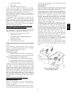
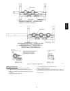
Step 10 —Flue Gas Passageways
To inspect the flue collector box and upper areas of the heat
exchanger:
1. Remove the combustion blower wheel and motor
assembly according to directions in Combustion-Air
Blower section below.
2. Remove the 3 screws holding the blower housing to the
flue cover.
3. Remove the flue cover to inspect the heat exchanger.
4. Clean all surfaces as required using a wire brush.
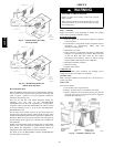
Step 11 —Combustion--Air Blower
Clean periodically to ensure proper airflow and heating
efficiency . Inspect blower wheel every f all and periodically
during heating season. For the first heating season, inspect blower
wheel bimonthly to determine proper cleaning frequency.
To inspect blower wheel, remove draft hood and screen. Shine a
flashlight into opening to inspect wheel. If cleaning is required,
remove motor and wheel as follows:
1. Slide burner access panel out.
2. Remove the 5 screws that attach induced-draft motor
assembly to the vestibule cover.
3. Slide the motor and blower wheel assembly out of the
blower housing. The blower wheel can be cleaned at this
point. If additional cleaning is required, continue with
Steps 4 and 5.
4. To remove blower from the motor shaft, remove
2setscrews.
5. To remove motor, remove the 4 screws that hold the
motor to mounting plate. Remove the motor cooling fan
48HE,HJ