


59
TROUBLESHOOTING
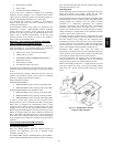
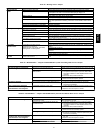
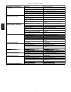
Step 1 —Unit Troubleshooting
Refer to Tables 35-39 for unit troubleshooting details.
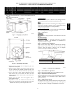
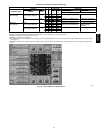
Step 2 —Economi$er IV Troubleshooting
See Table 40 for EconoMi$er IV logic.
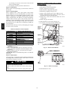
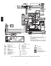
A functional view of the EconoMi$er IV is shown in Fig. 69.
Typical settings, sensor ranges, and jumper positions are also
shown. An EconoMi$er IV simulator program is available from
Carrier to help with EconoMi$er IV training and
troubleshooting.
Economi$er IV pr
eparation
This procedure is used to prepare the EconoMi$er IV for
troubleshooting. No troubleshooting or testing is done by
performing the following procedure.
NOTE: This procedure requires a 9-v battery, 1.2 kilo-ohm
resistor, and a 5.6 kilo-ohm resistor which are not supplied with
the EconoMi$er IV.
IMPORTANT: Be sure to record the positions of all
potentiometers before starting troubleshooting.
1. Disconnect power at TR and TR1. All LEDs should be
off. Exhaust fan contacts should be open.
2. Disconnect device at P and P1.
3. Jumper P to P1.
4. Disconnect wires at T and T1. Place 5.6 kilo-ohm resistor
across T and T1.
5. Jumper TR to 1.
6. Jumper TR to N.
7. If connected, remove sensor from terminals S
O
and +.
Connect 1.2 kilo-ohm 4074EJM checkout resistor across
terminals S
O
and +.
8. Put 620-ohm resistor across terminals S
R
and +.
9. Set minimum position, DCV set point, and exhaust
potentiometers fully CCW (counterclockwise).
10. Set DCV maximum position potentiometer fully CW
(clockwise).
11. Set enthalpy potentiometer to D.
12. Apply power (24 vac) to terminals TR and TR1.
differential
enthalpy
To check differential enthalpy:
1. Make sure EconoMi$er IV preparation procedure has been
performed.
2. Place 620-ohm resistor across S
O
and +.
3. Place 1.2 kilo-ohm resistor across S
R
and +. The Free
Cool LED should be lit.
4. Remove 620-ohm resistor across S
O
and +. The Free Cool
LED should turn off.
5. Return EconoMi$er IV settings and wiring to normal
after completing troubleshooting.
single
enthalpy
To check single enthalpy:
1. Make sure EconoMi$er IV preparation procedure has been
performed.
2. Set the enthalpy potentiometer to A (fully CCW). The
Free Cool LED should be lit.
3. Set the enthalpy potentiometer to D (fully CW). The Free
Cool LED should turn off.
4. Return EconoMi$er IV settings and wiring to normal
after completing troubleshooting.
dcv (demand controlled ventilation) a nd power
exhaust
To check DCV and Power Exhaust:
1. Make sure EconoMi$er IV preparation procedure has been
performed.
2. Ensure terminals AQ and AQ1 are open. The LED for
both DCV and Exhaust should be off. The actuator should
be fully closed.
3. Connect a 9-v battery to AQ (positive node) and AQ1
(negative node). The LED for both DCV and Exhaust
should turn on. The actuator should drive to between 90
and 95% open.
4. Turn the Exhaust potentiometer CW until the Exhaust
LED turns o ff. The LED should turn off when the
potentiometer is approximately 90%. The actuator should
remain in position.
5. Turn the DCV set point potentiometer CW until the DCV
LED turns off. The DCV LED should turn off when the
potentiometer is approximately 9v. The actuator should
drive fully closed.
6. Turn the DCV and Exhaust potentiometers CCW until the
Exhaust LED turns on. The exhaust contacts will close 30
to 120 seconds after the Exhaust LED turns on.
7. Return EconoMi$er IV settings and wiring to normal
after completing troubleshooting.
dcv minimum and maximum
position
To check the DCV minimum and maximum position:
1. Make sure EconoMi$er IV preparation procedure has been
performed.
2. Connect a 9-v battery to AQ (positive node) and AQ1
(negative node). The DCV LED should turn on. The
actuator should drive to between 90 and 95% open.
3. Turn the DCV Maximum Position potentiometer to
midpoint. The actuator should drive to between 20 and
80% open.
4. Turn the DCV Maximum Position potentiometer to fully
CCW. The actuator should drive fully closed.
5. Turn the Minimum Position potentiometer to midpoint.
The actuator should drive to between 20 and 80% open.
6. Turn the Minimum Position Potentiometer fully CW. The
actuator should drive fully open.
7. Remove the jumper from TR and N. The actuator should
drive fully closed.
8. Return EconoMi$er IV settings and wiring to normal
after completing troubleshooting.
supply --air
input
To check supply-air input:
1. Make sure EconoMi$er IV preparation procedure has been
performed.
2. Set the Enthalpy potentiometer to A. The Free Cool LED
turns on. The actuator should drive to between 20 and
80% open.
3. Remove the 5.6 kilo-ohm resistor and jumper T to T1. The
actuator should drive fully open.
4. Remove the jumper across T and T1. The actuator should
drive fully closed.
5. Return EconoMi$er IV settings and wiring to normal
after completing troubleshooting.
economi$er IV troubleshooting
completion
This procedure is used to return the EconoMi$er IV to operation.
No troubleshooting or testing is done by performing the
following procedure.
1. Disconnect power at TR and TR1.
2. Set enthalpy potentiometer to previous setting.
48HE,HJ