


8
C06114
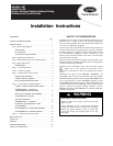
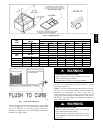
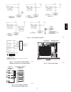
Fig. 10 --- Flue Hood Details
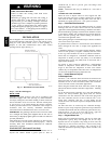
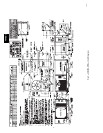
LEGEND
*
Field supplied.
NOTE: Follow all local codes.
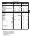
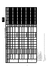
SPACING OF SUPPORTS
NFGC — National Fuel Gas Code
STEEL PIPE
NOMINAL DIAMETER (in.)
SPACING OF SUPPORTS
X DIMENSION (ft)
1
/
2
3
/
4
or 1
1
1
/
4
or larger
6
8
10
C06115
Fig. 11 --- Gas Piping Guide (With Accessory
Thru--the--Curb Service Connections)
Step 7 —Make Electrical Connections
ELECTRICAL SHOCK HAZARD
Failure to follow this warning could re sult in personal
injury or death.
Unit ca bi net must ha ve an unint errupted, unbr oken
electrica l gr ound to minimize the poss i b ility of personal
injury if an el ectrical f ault should occ ur. This ground may
consist of electrical wire connected to unit g round lug in
control c om partme nt , or c ondui t a pproved for e l ec tri ca l
ground when ins talled in accordance with NEC (National
Electrical Code), ANSI/NFP A (National Fire Protection
Association), latest e dition, and local electrical codes. Do
not use gas piping as an el ec t rical ground.
!
WARNING
field power supply
All units except 208/230-v units are factory wired for the voltage
shown on the nameplate. If the 208/230-v unit is to be connected
to a 208-v power supply, the transformer must be rewired by
moving the black wire from the 230-v terminal on the
transformer and connecting it to the 200-v terminal from the
transformer.
Refer to unit label diagram for additional information. Pigtails
are provided for field service. Use factory-supplied splices or UL
(Underwriters’ Laboratories) approved copper connector.
When installing units, provide a disconnect per NEC.
All field wiring must comply with NEC and local
requirements.
Install conduit through side panel openings indicated in Fig. 8.
Route power lines through connector to terminal connections as
shown in Fig. 12.
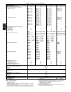
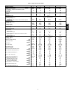
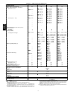
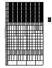
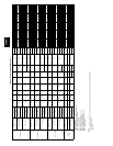
Voltage to compressor terminals during operation must be within
voltage range indicated on unit nameplate (also see Tables 3 and
4). On 3-phase units, voltages between phases must be balanced
within 2% and the current within 10%. Use the f ormula shown in
Tables 3 and 4, Note 3 to determine the percent voltage
imbalance. Operation on improper line voltage or excessive phase
imbalance constitutes abuse and may cause damage to electrical
components. Such operation would invalidate any applicable
Carrier warranty.
NOTE: I f accessory thru-the-bottom connections and roof curb
are used, refer to the Thru-the-Bottom Accessory Installation
Instructions for information on power wiring and gas connection
piping. The power wiring, control wiring and gas piping can be
routed through field-drilled holes in the basepan. The basepan is
specially designed and dimpled for drilling the access connection
holes.(SeeFig.2.)
field contr ol
wiring
Install a Carrier-approved accessory thermostat assembly
according to installation instructions included with the accessory.
Locate thermostat assembly on a solid wall in the conditioned
space to sense average temperature in accordance with thermostat
installation instructions.
Route thermostat cable or equivalent single leads of colored wire
from subbase terminals through connector on unit to low-voltage
connections (shown in Fig. 13 and 14).
Connect thermostat wires to matching screw terminals of
low-voltage connection board. (See Fig. 13 and 14.)
NOTE: For wire runs up to 50 ft, use no. 18 AWG (American
Wire Gauge) insulated wire (35_Cminimum).For50to75ft,use
no. 16 AWG insulated wire (35_C minimum). For over 75 ft, use
no. 14 AWG insulated wire (35_C minimum). All wire larger
than no. 18 AWG cannot be directly connected to the thermostat
and will require a junction box and splice at the thermostat.
Pass the control wires through the hole provided in the corner
post; then feed wires through the raceway built into the corner
post to the 24-v barrier located on the left side of the control box.
(See Fig. 15). The raceway provides the UL required clearance
between high and low-voltage wiring.
heat anticipator
settings
Set heat anticipator settings at 0.14 amp for first stage and 0.14
for second stage heating, when available.
48HE,HJ