


51
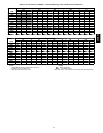
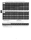
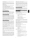
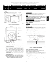
Table 39—Humidi-Mizer Adaptive Dehumidification System Sequence of Operation and
System Response — Single Compressor Unit (48HE003 --006, 48HJ004-007)
THERMOSTAT INPUT ECONOMIZER FUNCTION 48HE, HJ UNIT OPERATION
H Y1 Y2 OAT. < Economizer Set Point Economizer Comp. 1 Subcooling Mode Hot Gas Reheat Mode
Off — —
Normal Operation
On On On No Off On Yes No
On On Off No Off On Yes No
On On On Yes On On Yes No
On On Off Yes On On No Yes
On Off Off No Off On No Yes
NOTE: O n a thermostat call for W1, all cooling and dehumidification will be off.
LEGEND
OAT --- Outdoor Air Temperature
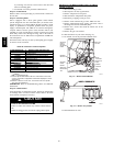
C06045
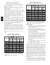
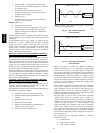
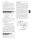
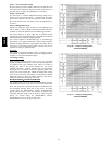
Fig. 57 --- Propping Up Top Panel
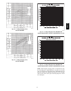
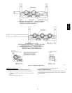
C06046
Fig. 58 --- Separating Coil Sections
4. Remove screws securing coil to compressor plate and
compressor access panel.
5. Remove fastener holding coil sections together at return
end of condenser coil. Carefully separate the outer coil
section 3 to 4 in. from the inner coil section. (See Fig. 58.)
6. Use a water hose or other suitable equipment to flush
down between the 2 coil sections to remove dirt and
debris. Clean the outer surfaces with a s tiff brush in the
normal manner.
7. Secure inner and outer coil rows together with a
field-supplied fastener.
8. Reposition the outer coil section and remove the coil
corner post from between the top panel and center post.
Reinstall the coil corner post and replace all screws.
condensate
drain
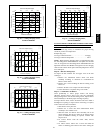
Check and clean each year at the start of the cooling season. In
winter, keep the drain dry or protect it against freeze-up.
filters
Clean or replace at the start of each heating and cooling season, or
more often if operating c onditions require it. Replacement f ilters
must be the same dimensions as the original filters.
outdoor-- air inlet scr
eens
Clean the screens with steam or hot water and a mild detergent.
Do not use disposable filters in place of screens.
Step 2 —Lubrication
compr
essor
The compressor is charged with the correct amount of oil at the
factory.
fan motor
bearings
Fan motor bearings are permanently lubricated. No further
lubrication is required. N o lubrica tion of c ondens er-fa n o r
evaporator-fan motors is required.
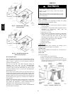
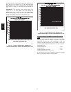
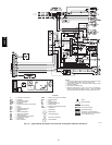
Step 3 —Condenser--Fan Adjustment
Shut off unit power supply. Remove condenser-fan assembly
(grille, motor, motor cover, and fan) and loosen fan hub
setscrews. Adjust fan height as shown in Fig. 59. Tighten
setscrews and replace condenser-fan assembly.
UNIT FAN HEIGHT (in.) — “A”
003-006 AND 007 (208/230 v) 2.75
007 (460 v) 3.50
C06138
Fig. 59 --- Condenser--Fan Adjustment
Step 4 —EconoMi$er IV Adjustment
Refer to Optional EconoMi$er IV and EconoMi$er2 section.
Step 5 —Evaporator Fan Belt Inspection
Check con-dition of evaporator belt or tension during heating and
cooling inspections or as conditions require. Replace belt or
adjust as necessary.
Step 6 —High Pressur e Switch
The high-pressure switch contains a Schrader core depressor, and
is located on the compressor hot gas line. This switch opens at
428 psig and closes at 320 psig. No adjustments are necessary.
48HE,HJ