


63
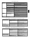
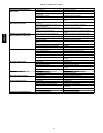
Table 46—EconoMi$er IV Input/Output Logic
INPUTS OUTPUTS
Demand Control
Ventilation (DCV)
Enthalpy*
Y1 Y2
Compressor NTerminal†
Outdoor Return
Stage
1
Stage
2
Occupied Unoccupied
Damper
Below set
(DCV LED O ff)
High
(F ree Cooling LED Off)
Low On On On On Minimum position Closed
On Off On Off
Off Off Off Off
Low
(F ree Cooling LED On)
High On On On Off Modulating** (between min.
position and full-open)
Modulating** (between
closed and full-open)
On Off Off Off
Off Off Off Off Minimum position Closed
Above set
(DCV LED On)
High
(F ree Cooling LED Off)
Low On On On On Modulating†† (between min.
position and DCV maximum)
Modulating†† (between
closed and DCV
maximum)
On Off On Off
Off Off Off Off
Low
(F ree Cooling LED On)
High On On On Off Modulating*** Modulating†††
On Off Off Off
Off Off Off Off
*For singleenthalpy control,themodulecomparesoutdoorenthalpyto theABCDsetpoint.
†Power at N terminal determines Occupied/Unoccupied setting: 24 vac (Occupied), no power (Unoccupied).
**Modulation is based on the supply-air sensor signal.
††Modulation is based on the D CV signal.
***Modulation isbased on the greater of DCV and supply-air sensor signals, between minimum position and either maximum position (DCV) or fully open (sup-
ply-air s i gnal).
†††Modulation isbased on the greater of DCV and supply-air sensor signals, between closed and either maximum position (DCV) or fully open (supply-airsig-
nal).
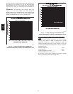
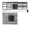
C06053
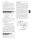
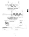
Fig. 76 --- EconoMi$er IV Functional View
48HE,HJ