


5
C06111
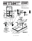
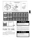
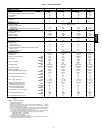
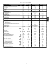
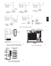
Fig. 6 --- Rigging Details
UNIT
48HE
OPERATING
WEIGHT
DIMENSIONS
“A” “B” “C”
lb kg in. mm in. mm in. mm
003 530 240 73.69 1872 35.50 902 33.31 847
004 540 245 73.69 1872 35.50 902 33.31 847
005 560 254 73.69 1872 35.50 902 33.31 847
006 635 288 73.69 1872 35.50 902 33.31 847
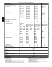
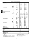
UNIT
48HJ
OPERATING
WEIGHT
DIMENSIONS
“A” “B” “C”
lb kg in. mm in. mm in. mm
004 530 240 73.69 1872 35.50 902 33.31 847
005 540 245 73.69 1872 35.50 902 33.31 847
006 560 254 73.69 1872 35.50 902 33.31 847
007 635 288 73.69 1872 35.50 902 33.31 847
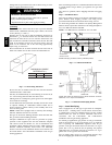
C06208
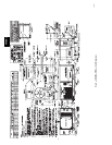
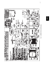
Fig. 7 --- Roof Curb Alignment
Support gas piping as shown in the table in Fig. 11. For example,
a
3
/
4
-in. gas pipe must have one field-fabricated support beam
every 8 ft. Therefore, an 18-ft long gas pipe would have a
minimum of 3 support beams, and a 48-ft long pipe would have a
minimum of 6 support beams.
PROPERTY DAMAGE HAZARD
Failure to follow this warning could result in personal
injury, death and property damage.
All panels must be in place when rigging and lifting.
!
WARNING
See Fig. 11 for typical pipe guide and locations of external
manual gas shutoff valve.
NOTE: I f accessory thru-the-bottom connections and roof curb
are used, refer to the Thru-the-Bottom Accessory Installation
Instructions for information on power wiring and gas
connection piping. The power wiring, control wiring and gas
piping can be routed through field-drilled holes in the basepan.
The basepan is specially designed and dimpled for drilling the
access connection holes.
FIRE, EXPLOSION HAZARD
Failure to follow this warning could result in personal
injury, death and/or property damage.
When connecting the gas line to the unit gas valve, the
installer MUST use a backup wrench to prevent damage
to the valve.
!
WARNING
48HE,HJ