


26
Differential Enthalphy Control
For differential enthalpy control, the EconoMi$er IV controller
uses two enthalpy sensors (HH57AC078 and
CRENTDIF004A00), one in the outside air and one in the return
air duct. The EconoMi$er IV controller compares the outdoor
air enthalpy to the return air enthalpy to determine EconoMi$er
IV use. The controller selects the lower enthalpy air (return or
outdoor) for cooling. For example, when the outdoor air has a
lower enthalpy than the return air, the EconoMi$er IV opens to
bring in outdoor air for free cooling.
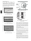
0
500
1000
1500
2000
2500
0.05
0.15
0.25
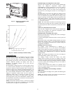
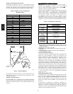
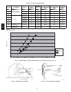
STATIC PRESSURE (in. wg)
FLOW IN CUBIC FEET PER MINUTE (cfm)
C06030
Fig. 38 --- Barometric Flow Capacity
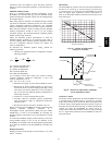
0
5
10
15
20
25
30
0.13 0.20 0.22 0.25 0.30 0.35 0.40 0.45 0.50
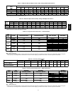
STATIC PRESSURE (in. wg)
FLOW IN CUBIC FEET PER MINUTE (cfm)
C06031
Fig. 39 --- Outdoor-- Air Damper Leakage
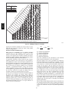
0
1000
2000
3000
4000
5000
6000
0.05 0.10 0.15 0.20 0.25 0.30 0.35
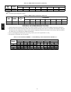
STATIC PRESSURE (in. wg)
FLOW IN CUBIC FEET PER MINUTE (cfm)
C06032
Fig. 40 --- Return -- Air Pressure Dro p
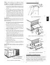
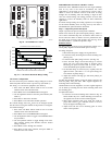
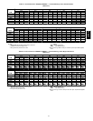
SUPPLY AIR
TEMPERATURE
SENSOR
MOUNTING
LOCATION
SUPPLY AIR
TEMPERATURE
SENSOR
C06033
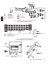
Fig. 41 --- Supply Air Sensor Location
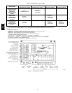
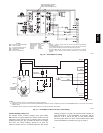
C06034
Fig. 42 --- EconoMi$er IV Contro ller Potentiometer
and LED Locations
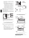
Replace the standard outside air dry bulb temperature sensor with
the accessory enthalpy sensor in the same mounting location.
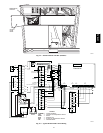
(See Fig. 29.) Mount the return air enthalpy sensor in the return
air duct. (See Fig. 44.) Wiring is provided in the EconoMi$er IV
wiring harness. (See Fig. 36.) The outdoor enthalpy changeover
set point is set with the outdoor enthalpy set point potentiometer
on the EconoMi$er IV controller. When using this mode of
changeover control, turn the enthalpy setpoint potentiometer fully
clockwise to the D setting.
Indoor Air Quality (IAQ) Sensor Input
The IAQ input can be used for demand control ventilation control
based on the level of CO
2
measured in the space or return air
duct.
Mount the accessory IAQ sensor according t o manufacturer
specifications. The IAQ sensor should be wired to the AQ and
AQ1 terminals of the controller. Adjust the DCV potentiometers
to correspond to the DCV voltage output of the indoor air quality
sensor at the user-determined set point. (See Fig. 47.)
If a separate field-supplied transformer is used to power the IAQ
sensor, the sensor must not be grounded or the EconoMi$er IV
control board will be damaged.
Exhaust Set Point Adjustment
The exhaust set point will determine when the exhaust fan runs
based on damper position (if accessory power exhaust is
installed). The set point is modified with the Exhaust Fan Set
Point (EXH SET) potentiometer. (See Fig. 42.) The set point
represents the damper position above which the exhaust fans will
be turned on. When there is a call for exhaust, the EconoMi$er IV
controller provides a 45 15 second delay before exhaust fan
48HE,HJ