


46
2. Turn off power to the unit and tag disconnect.
3. Reverse any two of the unit power leads.
4. Turn on power to the unit and energize the compressor.
The suction and discharge pressure levels should now move to
their normal start-up levels.
NOTE: When the compressor is rotating in the wrong direction,
the unit makes more noise and does not provide cooling.
Step 10 —Cooling
Set the space thermostat to the OFF position. Set the system
selector switch at COOL position and the fan switch at AUTO
position. Adjust the thermostat to a setting below room
temperature. The compressor starts when contactor closes.
Check the unit charge. Refer to Refrigerant Charge section.
Reset the thermostat at a position above room temperature. The
compressor will shut off. Evaporator fan will shut off after a
30--second delay.
To Shut Off Unit -- Set the system selector switch at OFF
position. Resetting the thermostat at a position above room
temperature shuts off the unit temporarily until the space
temperature exceeds the thermostat setting. Units are equipped
with a Cycle-LOC protection device. The unit shuts down on
any safety trip and remains off; an indicator light on the
thermostat comes on. Check the reason for the safety trip.
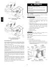
Step 11 —Main Burners
Main burners are factory set and should require no adjustment.
TO CHECK ignition of main burners and heating controls, move
thermostat set point above room temperature and verify that the
burners light and evaporator fan is energized. Check heating
effect, then lower the thermostat setting below the room
temperature and verify that the burners and evaporator fan turn
off.
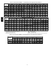
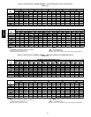
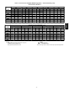
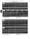
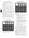
Refer to Tables 37 and 38 for the correct orifice to use at high
altitudes.
Table 37—Altitude Compensation*
48HJ004--007, 48HE003 --006 Standard Units
ELEVATION
(ft)
72,000 AND
115,000 BTUH
NOMIN
A
LINPUT
150,000 BTUH
NOMINAL INPUT
Natural
Gas
Orifice
Size†
Liquid
Propane
Orifice
Size†
Natural
Gas
Orifice
Size†
Liquid
Propane
Orifice
Size†
0-2,000
33 43 30 37
2,000
36 44 31 39
3,000
36 45 31 40
4,000
37 45 32 41
5,000
38 46 32 42
6,000
40 47 34 43
7,000
41 48 35 43
8,000
42 49 36 44
9,000
43 50 37 45
10,000
44 50 39 46
11,000
45 51 41 47
12,000
46 52 42 48
13,000
47 52 43 49
14,000
48 53 44 50
*Asthe height above sea level increases, thereis less oxygen per cubic
footof air. Therefore, heat input rateshould be reduced at higher alti-
tudes.
†Orifices available through your Carrier distributor.
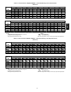
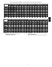
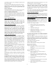
Table 38—Altitude Compensation* —
48HJ004-006, 48HE003 --006 Low NOx Units
ELEVATION
(ft)
60,000 AND
90,000 BTUH
NOMINAL INPUT
120,000 BTUH
NOMINAL INPUT
Natural
Gas
Orifice
Size†
Liquid
Propane
Orifice
Size†
Natural
Gas
Orifice
Size
Liquid
Propane
Orifice
Size†
0-2,000
38 45 32 42
2,000
40 47 33 43
3,000
41 48 35 43
4,000
42 49 36 44
5,000
43 49 37 45
6,000
43 50 38 45
7,000
44 50 39 46
8,000
45 51 41 47
9,000
46 52 42 48
10,000
47 52 43 49
11,000
48 53 44 50
12,000
49 53 44 51
13,000
50 54 46 52
14,000
51 54 47 52
*Asthe height above sea level increases, there is less oxygen per cubic
foot of air. Therefore, the input rate should be reduced at h igher alti-
tudes.
†Orifices are available through your local Carrier distributor.
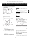
Step 12 —Heating
1. Purge gas supply line of air by opening union ahead of the
gas valve. If gas odor is detected, tighten union and wait 5
minutes before proceeding.
2. Turn on electrical supply and manual gas valve.
3. Set system switch selector at HEAT position and fan
switch at AUTO or ON position. Set heating temperature
lever above room temperature.
4. The induced-draft motor will start.
5. After a call for heating, the main burners should light
within 5 seconds. If the burner does not light, then there is
a 22-second delay before another 5-second try. If the
burner still does not light, the time delay is repeated. If the
burner does not light within 15 minutes, there is a lockout.
To reset the control, break the 24 v power to W1.
6. The evaporator-fan motor will turn on 45 seconds after
burner ignition.
7. The evaporator-fan motor will turn off in 45 seconds after
the thermostat temperature is satisfied.
8. Adjust airflow to obtain a temperature rise within the
range specified on the unit nameplate.
NOTE: The default value for the evaporator-fan motor on/off
delay is 45 seconds. The Integrated Gas Unit Controller (IGC)
modifies this value when abnormal limit switch cycles occur.
Based upon unit operating conditions, the on delay can be
reduced to 0 seconds and the off delay can be extended to 180
seconds. When one flash of the LED (light-emitting diode) is
observed, the evaporator-fan on/off delay has been modified.
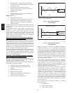
If the limit switch trips at the start of the heating cycle during the
evaporator on delay, the time period of the on delay for the next
cycle will be 5 seconds less than the time at which the switch
tripped. (Example: If the limit switch trips at 30 seconds, the
evaporator-fan on delay for the next cycle will occur at 25
seconds.) To prevent short-cycling, a 5-second reduction will
only occur if a minimum of 10 minutes has elapsed since the last
call for heating.
The evaporator-fan off delay can also be modified. Once the call
for heating has ended, there is a 10-minute period during which
the modification can occur. If the limit switch trips during this
period, the evaporator-fan off delay will increase by 15 seconds.
48HE,HJ