


49
S SPT reading is available
S OAT ± SPT
S Economizer Position is NOT forced
If any of the above conditions are not met, the economizer
submaster reference (ECSR) is set t o maximum limit and the
damper moves to minimum position. The operating sequence is
complete. The ECSR is recalculated every 30 seconds.
If an optional power exhaust is installed, as the outdoor-air
damper opens and closes, the power exhaust fans will be
energized and deenergized.
If field-installed accessory CO
2
sensors are connected to the
PremierLink control, a PID-controlled demand ventilation
strategy will begin to operate. As the CO
2
level in the zone
increases above the CO
2
set point, the minimum position of the
damper will be increased proportionally. As the CO
2
level
decreases because of the increase in fresh air, the outdoor-air
damper will be proportionally closed.
HEATING -- UNIT WITH ECONOMI$ER2,
PREMIER-
LINK CONTROL AND A ROOM
SENSOR
Every 40 seconds the controller will calculate the required heat
stages (maximum of 3) to maintain Supply-Air Temperature
(SAT) if the following qualifying conditions are met:
S Indoor fan has been on for at least 30 seconds.
S COOL mode is not active.
S OCCUPIED, TEMP. COMPENSATED START or
HEAT mode is active.
S SAT reading is available.
S Fire shutdown mode is not active.
If all of the above conditions are met, the number of heat stages is
calculated; otherwise the required number of heat stages will be
set to 0.
If the PremierLink controller determines that heat stages are
required, the economizer damper will be moved to minimum
position if occupied and closed if unoccupied.
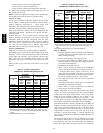
Staging should be as follows:
If Heating PID STAGES=2
S HEAT ST AGES=1 (50% capacity) will energize HS1
S HEAT STAGES=2 (100% capacity) will energize HS2
If Heating PID STAGES=3 and AUXOUT = HS3
S HEAT ST AGES=1 (33% capacity) will energize HS1
S HEAT ST AGES=2 (66% capacity) will energize HS2
S HEAT STAGES=3 (100% capacity) will energize HS3
In order to prevent short cycling, the unit is locked into the
Heating mode for at least 10 minutes when HS1 is deenergized.
When HS1 is ener gized the induced-draft motor is then
energized and the burner ignition sequence begins. On units
equipped for two stages of heat, when additional heat is needed,
HS2 is energized and the high-fire solenoid on the main gas valve
(MGV) is energized. When the space condition is satisfied and
HS1 is deenergized the IFM stops after a 45-second time-off
delay unless in the occupied mode. The fan will run continuously
in the occupied mode as required by national energy and fresh air
standards.
UNITS WITH HUMIDI-MIZER
ADAPTIVE
DEHUMIDIFICATION
SYSTEM
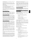
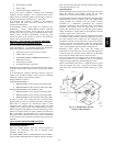
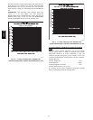
Normal Design Operation
When the rooftop operates under the normal sequence of
operation, the compressors will cycle to maintain indoor
conditions. (See Fig. 53.)
The Humidi-MiZer adaptive dehumidification system includes a
factory-installed Motormaster low ambient control to keep the
head and suction pressure high, allowing normal design cooling
mode operation down to 0 F.
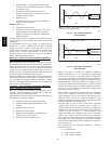
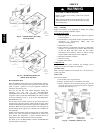
Subcooling Mode
When subcooling mode is initiated, this will ener gize (close) the
liquid line solenoid valve (LLSV) forcing the hot liquid
refrigerant to enter into the subcooling coil. (See Fig. 54.)
As the hot liquid refrigerant passes through the subcooling/ reheat
dehumidification coil, it is exposed to the cold supply airflow
coming through the evaporator coil. The liquid is further
subcooled to a temperature approaching the evaporator
leaving-air temperature. The liquid then enters a thermostatic
expansion valve (TXV) where the liquid drops to a lower
pressure. The TXV does not have a pressure drop great enough to
change the liquid to a 2-phase fluid, so the liquid then enters the
Acutrol device at the evaporator coil.
The liquid enters the evaporator coil at a temperature lower than
in standard cooling operation. This lower temperature increases
the latent capacity of the rooftop unit. The refrigerant passes
through the evaporator and is turned into a vapor. The air passing
over the evaporator coil will become colder than during normal
operation. However, as this same air passes over the subcooling
coil, it will be slightly warmed, partially reheating the air.
Subcooling mode operates only when the outside air
temperature is warmer than 40_F. A factory-installed temperature
switch located in the condenser section will lock out subcooling
mode when the outside temperature is cooler than 40_F.
The scroll compressors are equipped with crankcase heaters to
provide protection for the compressors due to the additional
refrigerant charge required by the subcooling/reheat coil.
When in subcooling mode, there is a slight decrease in system
total gross capacity (5% less), a lower gross sensible capacity
(20% less), and a greatly increased latent capacity (up to 40%
more).
C06135
Fig. 53 --- Humidi-- MiZer Normal
Design Cooling Operation
48HE,HJ