


25
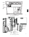
FOR OCCUPANCY CONTROL
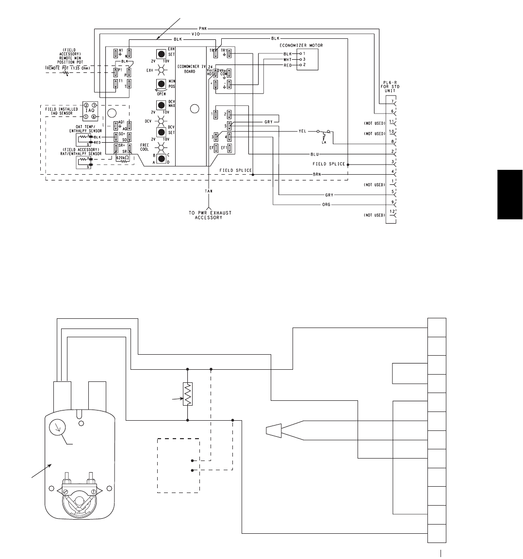
REPLACE JUMPER WITH
FIELD-SUPPLIED TIME CLOCK
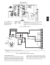
LEGEND
DCV— Demand Controlled Ventilation
IAQ — Indoor Air Quality
LA — Low Ambient Lockout Device
OA T— Outdoor-Air Temperature
POT—Potentiometer
RAT—Return-Air Temperature
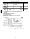
Potentiometer Defaults Settings:
Power Exhaust Middle
Minimum Pos. Fully Closed
DCV Max. Middle
DCV Set Middle
Enthalpy C Setting
NOTES:
1. 620 ohm, 1 watt 5% resistor should be removed only when using differential
enthalpy or dry bulb.
2. If a separate field-supplied 24 v transformer is used for the IAQ sensor power
supply, it cannot have the secondary of the transformer grounded.
3. For field-installed remote minimum position POT, remove black wire jumper
between P and P1 and set control minimum position POT to the minimum
p
osition.
C06028
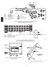
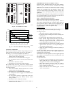
Fig. 36 --- EconoMi$er IV Wiring
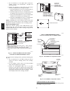
4
3
5
2
8
6
7
1
10
11
9
12
PINK
VIOLET
BLACK
BLUE
YELLOW
NOTE 1
NOTE 3
RUN
500 OHM
RESISTOR
-
+
OPTIONAL CO
SENSOR4-20mA
OUTPUT
50HJ540573
ACTUATOR
ASSEMBLY
RED
WHITE
ECONOMISER2 PLUG
DIRECT DRIVE
ACTUATOR
2
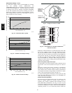
NOTES:
1. Switch on actuator must be inrun position for economizer to operate.
2. PremierLink™ control requires that the standard 50HJ540569 outside-air sensor be replaced by either the CROASENR001A00 dry bulb sensor or HH57A077
enthalpy sensor.
3. 50HJ540573 actuator consists of the 50HJ540567 actuator and a harness with 500-ohm resistor.
C06029
Fig. 37 --- EconoMi$er2 with 4 to 20 mA Control Wiring
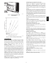
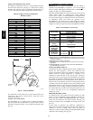
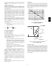
Outdoor Enthalpy Changeover
For enthalpy control, accessory enthalpy sensor (part number
HH57AC078) is required. Replace the standard outdoor dry bulb
temperature s ensor with the accessory enthalpy sensor in the s ame
mounting location. (See Fig. 29.) When the outdoor air enthalpy
rises above the outdoor enthalpy changeover set point, the
outdoor-air damper moves to its minimum position. The outdoor
enthalpy changeover set point is set with the outdoor enthalpy set
point potentiometer on the EconoMi$er IV controller. The set
points are A, B, C, and D. (See Fig. 45.) The factory-installed
620-ohm jumper must be in place across terminals SR and SR+
on the EconoMi$er IV controller. (See Fig. 29 and 46.)
48HE,HJ