


RH-981A
CONTENTS
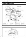
1. NAMES OF EACH PART
................................ 1
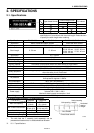
2. SPECIFICATIONS
.............................................. 2
2-1. Specifications ...................................................... 2
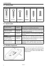
2-2. Sewing shape ..................................................... 3
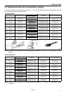
2-3. Optional parts ...................................................... 3
2-4. PD-9810, Programmer ....................................... 3
2-5. Replacement parts list for
specification changes ......................................... 4
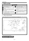
3. INSTALLATION
.................................................... 5
3-1. Table processing diagram ................................ 5
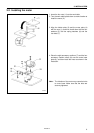
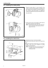
3-2. Installing the motor ............................................ 6
3-3. Installing the motor pulley ................................. 7
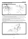
3-4. Installing the control box ................................... 7
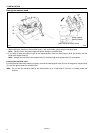
3-5. Installing the machine head .............................. 8
3-6. Installing the oil container ............................... 10
3-7. Installing the operation panel .......................... 10
3-8. Tightening the V-belt ....................................... 11
3-9. Installing the spool stand ................................ 12
3-10.Installing the hand switch ................................ 12
3-11.Installing the air unit and the valve unit .......... 12
3-12.Connecting the wiring ...................................... 13
3-12-1. Connections inside the control box ......... 14
3-12-2. Connecting the motor cables................... 15
3-12-3. Connecting the air tubes.......................... 15
3-12-4. Securing the cables.................................. 16
3-13.Connecting the air tubes ..................................17
3-13-1. Adjusting the air pressure ........................ 17
3-14.Connecting the power cord ............................. 18
3-15.Installing the programmer
(sold separately)............................................... 19
3-16.Installing the foot switch (option) ..................... 19
3-17.Installing the indexer (option) .......................... 20
3-17-1. Installing the indexer main unit................ 20
3-17-2. Installing the upper thread presser ......... 21
3-17-3. Replacing the plate presser and
presser plate ............................................ 21
3-17-4. Installing the valve unit ................................ 21
3-17-5. Connecting the connectors.......................... 22
3-17-6. Connecting the air tubes ............................. 23
3-17-7. Securing the air tubes and cables............... 23
3-17-8. Installing the hand switch............................. 24
4. LUBRICATION
...................................................... 25
4-1. Adding oil ......................................................... 25
4-2. Lubrication ....................................................... 25
5. CORRECT USE
................................................. 27
5-1. Data initialization............................................... 27
5-2. Changing the lower thread and
gimp trimming .................................................. 27
5-3. Installing the needle ......................................... 28
5-4. Threading the upper thread ............................. 28
5-5. Threading the lower thread.............................. 29
5-6. Threading the gimp ......................................... 30
5-7. Setting the material .......................................... 31
5-8. Setting the installation position
for cloth feed plate (L) (-52 specifications) ...... 33
5-9. Replacing the PROMs ..................................... 34
6. OPERATION
......................................................... 35
6-1. Name and function of
each operation panel item................................ 35
6-2. Starting up......................................................... 36
6-3. Program setting method .................................. 37
6-3-1. Parameter table ( Taper bar ) ..................... 37
6-3-2. Parameter table ( Straight bar tacking ) ......40
6-4. Cycle program .................................................. 43
6-5. Production counter ........................................... 44
6-6. Using the program memos .............................. 44
7. SEWING
................................................................ 45
7-1. Automatic sewing ............................................. 45
7-2. Using the EMERGENCY STOP switch ......... 46
7-3. Adjusting the thread tension ............................ 47
7-4. Needle and knife position................................. 48
7-5. Setting the feed bracket to
the front position............................................... 49
7-6. Switching between single-pedal
and dual-pedal operation ................................. 49
7-7. Using test feed mode ....................................... 50
7-8. Using manual mode ......................................... 51
7-9. Changing the mode during an operation ........ 52
7-10.Moving the cloth feed bar
(-52 specifications) ........................................... 52
8.
CLEANING AND MAINTENANCE
............
53
8-1. Cleaning ........................................................... 53
8-2. Draining the oil ................................................. 54
8-3. Checking the air filter........................................ 54
9. STANDARD ADJUSTMENTS
....................... 55
9-1. Adjusting the height of the
spreader and looper......................................... 55
9-2. Adjusting the needle and looper timing........... 56
9-3. Adjusting the loop stroke.................................. 57
9-4. Adjusting the height of the needle bar............. 58