


3. INSTALLATION
RH-981A
22
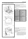
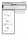
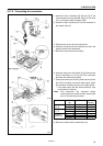
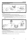
3-17-5. Connecting the connectors
1. Insert the 3-pin connectors [8], [9] and [10] of the
valve harness into the solenoid valves of the valve
unit (1) so that the label numbers match.
2. Insert the 15-pin connector (2) into the connector of
the indexer cord (3).
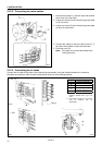
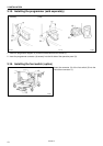
3. Open the rear cover (4) of the control box.
4. Insert the connector (5) of the indexer cord (3) in the
position shown in the illustration.
5. Secure the cord with the cord clamp.
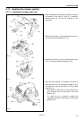
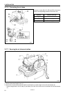
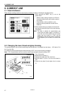
6. Insert the two pins of limit switch (R) (6) and the two
pins of limit switch (L) (7) into the 15-pin connector
terminals with matching numbers.
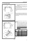
7. Connect the three pins of the cylinder sensor (8) into
the 15-pin connector so that the cable colors match
the connector numbers as given in the table below.
* If the cable colors are red, white and black, refer
to the colors in brackets.
Note: First disconnect the connector before
inserting the pins, and then after inserting the
pins, re-connect the connector.
Switch pin
No.
Cable color
15-pin
Connector
7White7
Limit switch
(R) (6)
12 Black 12
10 White 10
Limit switch
(L) (7)
15 Black 15
Brown (Red) 4
Black (White) 9
Cylinder
sensor (8)
Blue (Black) 14
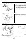
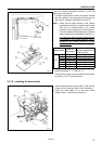
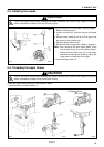
8. Secure the cable with the cable clamp (9).
3023Q
3024Q
3025Q