


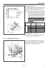

3. INSTALLATION
RH-981A
24
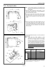
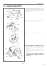
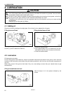
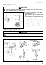
Insert the indexer specification harness (1) into the
control box connector (2).
* If another specification harness has been inserted
into this connector, first disconnect this harness and
then insert the indexer specification harness (1).
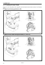
Note: Check that the label number on the indexer
specification harness (1) matches the movable
knife (R) (3), movable knife (L) (4), thread
handler (5), work clamp (R) (6), work clamp (L)
(7) and movable knife driving cam (8) numbers
before inserting the specification harness (1).
(If a connector with an incorrect label number
is connected, it may cause problems such as
damage to the sewing machine or thread
trimming errors.)
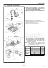
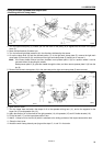
Specification
Label No.
of harness
Right/left work clamp No.
Right/left movable knife No.
Thread handler No.
L1 1 1
L2 2 2
L3 3 3
L4 4 4
L5 5 5
L6 6 6
-52
L7 7 7
* There is 10 mm of difference in the knife installation
positions between L1 - L4 and L5 - L7.
* If using both an upper thread clamping device and a
fly indexer, L5 to L7 cannot be used.
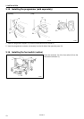
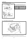
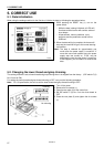
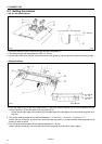
3-17-8. Installing the hand switch
1. Install the hand switch support plate (1) with the two
screws (2) in the position shown in the illustration.
2. Install the hand switch (3) to the hand switch
support plate (1) with the two screws (4).
3003Q
3004Q
3027Q