


3. INSTALLATION
RH-981A
14
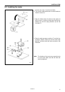
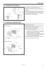
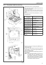
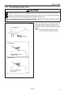
3-12-1. Connections inside the control box
1. Open the rear cover (1) of the control box.
2. Pass the cables through the holes (2) and (3) in the
side of the control box.
3. Loosen the screw (5), and then connect the three
ground cables (4) that are coming from the machine
head.
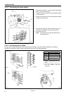
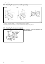
4. Securely insert each of the connectors (6) - (14) as
indicated below.
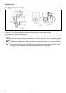
Machine head
connectors
(Connection indications)
* This is indicated on the P.C. board.
Connector (6)
(12-pin with [1] mark)
P1 (ORG)
Connector (7)
(5-pin with [2] mark)
P2 (SYNCHRO)
Connector (8)
(9-pin with [3] mark)
P3 (HEAD)
Connector (9)
(12-pin with [4] mark)
P4 (AIR)
Connector (10)
(5-pin with [6] mark)
P6 (YPM) (BLUE)
Connector (11)
(5-pin with [7] mark)
P7 (XPM)
Connector (12)
(16-pin with [8] mark)
P8 (EXINA)
Connector (13)
(18-pin with [9] mark)
P9 (EXINB)
Connector (14)
(10-pin)
P18 (PANEL)
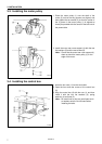
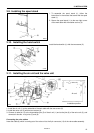
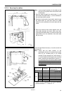
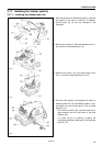
5. Insert the connector (15) (6-pin with [1][R] mark) to
the connector (16).
6. Loosen the middle screw (19) and then install the
ground cable (17) and the three ground cables (18)
from the operation panel.
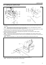
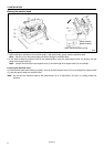
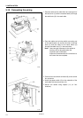
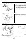
7. Secure the cables with the cable clamp as shown in
the illustration.
Note: When securing the cables, do not let any of
the cables touch the components on the
circuit board or the heat sink. Furthermore,
adjust the lengths of the cables from outside
the control box so that there is no looseness
in the cables inside the control box.
2997Q
2998Q
2999Q
PMD circuit
Board