


ICP-CC488 | Installation Guide | 22.0 Terminals and Descriptions EN | 92
Bosch Security Systems, Inc. | 12/08 | F01U089457-02
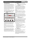
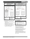
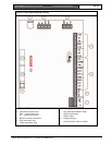
22.0 Terminals and Descriptions
22.1 Terminal Descriptions
Table 63: Terminal Descriptions
Terminal Description
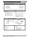
EARTH Connect this terminal to the green wire on the TF008 Plug Pack that is internally connected to
MAINS earth. Because extensive lightning protection is built into the control panel, this
terminal must be connected correctly to take advantage of this protection.
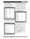
18 VAC These two terminals are plug-on type, and are the termination point for the TF008 plug pack.
To ensure correct operation, the voltage of the plug pack must be 18 VAC to 22 VAC at 1.3
A (minimum).
+BATTERY
–BATTERY
The +BATTERY terminal connects to the red positive terminal of the battery and the –
BATTERY terminal connects to the black negative terminal of the battery. The battery should
be a 12 VDC sealed lead-acid rechargeable type with a capacity from 1.2 Ah to 6.5 Ah. The
battery is protected by a 2.5 A PTC.
The charging globe situated above the 2.5 A PTC is always lit until the battery is 100%
charged.
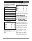
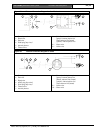
GND
+12V
CLK
DATA
This group of terminals provides the connection points for your system codepads. All system
codepads should connect in a parallel configuration back to these terminals. The only factor
restricting the number of codepads that can be connected is the available power and its
distribution. Since each codepad has a maximum power requirement of 60 mA with all
indicators lit, take this into consideration to calculate your available continuous power. The
total continuous external load should not exceed 1 A.
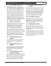
STR
OUT 1
+COM
These terminals are the output interface terminals. They can be configured to any combination
of the functions available through the system programming options. You can use them for a
variety of functions with considerable flexibility. All outputs have a common +12 VDC terminal
and each output can sink up to 400 mA. By default, Output 1 operates a horn speaker.
This group of terminals is protected by the solid-state IPS system, which provides
considerable tolerance to abuse or incorrect wiring. Each output is open collector and does
not source any current, but it can sink up to 400 mA per output.
COMM
N/O
These relay contacts are fully programmable similar to the strobe and Output 1. By default,
they are an alarm output (Sirens Running – Output Event Type 1,15).
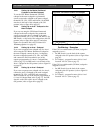
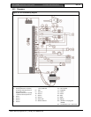
The N/O contact is the connection point for the positive side of a DC siren, such as a piezo
screamer. The negative side of the DC siren connects to the GND terminal. The PCB
provides a link (JP2) to connect the COM terminal to either GND or +12 V. Connect this link
to +12 V as shown in Figure 23 on page 95. The relay is rated at 1 A/30 VDC.
+12V
Z4
Z3
These terminals are provided for Zones 3 and 4. The common terminal is +12V. Connect all
normally-closed contacts in series with the EOL resistor and connect all normally-open
contacts in parallel with the EOL resistor. The function of the zones and their response times
are configured using the system programming options. If split EOL is programmed, 24-Hour
Zones or Keyswitch Zones connected in parallel to Zones 3 and 4 act as Zones 7 and 8.
+12V
GND
These two terminals are provided to power detectors and other equipment. They are fuse-
protected by the 1 A PTC.
Z2
Z1
+12V
These terminals are provided for Zones 1 and 2. The common terminal is +12V. Connect all
normally-closed contacts in series with the EOL resistor and connect all normally-open
contacts in parallel with the EOL resistor. The function of the zones and their response times
are configured using the system programming options. If split EOL is programmed, 24-Hour
Zones or Keyswitch Zones connected in parallel to Zones 1 and 2 act as Zones 5 and 6.