


ICP-CC488 | Installation Guide | 2.0 Codepad Indicators EN | 13
Bosch Security Systems, Inc. | 12/08 | F01U089457-02
Table 10: Area On/Off Indicators
Indicator Definition
On
The area is armed in AWAY
Mode or STAY Mode 1.
Off The area is disarmed.
Area Display Indicators
The group of four Area Display indicators shows the
area to which the eight zones belong. For example, if
the Area 1 indicator is lit, the Zones indicators
correspond to the zones assigned to that area.
Press [AWAY] to move to the next area display. For
example, if the Area 1 indicator is lit, pressing
[AWAY] extinguishes the Area 1 indicator and lights
the Area 2 indicator.
Table 11: Area Display Indicators
Indicator Definition
On Information is displayed for the area.
Off Information is not displayed for the area.
AUX Indicator
If Options 8 is selected in Location 500 (refer to
Section 19.3.1 Partitioning Options 1 on page 85), the
AUX indicator lights when the control panel is using
the telephone line. The AUX indicator also flashes
with the PARTIAL indicator when Installer’s
Programming Mode or Master Code functions are
used.
Table 12: AUX Indicator
Indicator Definition
On
The control panel is using the
telephone line.
Off
The control panel is not using the
telephone line.
Flashing
Installer’s Programming Mode or a
Master Code function is active.
MAINS Indicator
The MAINS indicator shows the status of the AC
MAINS supply (refer to Table 6 on page 11).
When programming in Installer’s Programming
Mode or using a Master Code function, the MAINS
indicator lights to indicate a location value from 10 to
15. The MAINS indicator represents the 10 digit,
which is added to the value of the lit zone indicator
(for example, if the value programmed in a location
is 12, the MAINS and Zone 2 indicators light).
FAULT indicator
The FAULT indicator lights when the system detects
a system fault (refer to Table 7 on page 11). Refer to
Section 3.12 Fault Analysis Mode on page 18 for more
information on system faults.
Each time a new system fault is detected (the FAULT
indicator flashes), the codepad beeps once per min.
Press [AWAY] to stop the beeping and to
acknowledge the fault.
PARTIAL Indicator
The PARTIAL indicator lights when the system is
armed in STAY Mode 1. The PARTIAL indicator
flashes with the AUX indicator when Installer’s
Programming Mode or a Master Code function is
active. Refer to Table 13 on page 13.
Table 13: PARTIAL Indicator
Indicator Definition
On The system is armed in STAY Mode 1.
Off The system is not armed in STAY Mode 1.
Flashing
Installer’s Programming Mode or a Master
Code function is active.
Audible Indicators
The codepad provides a number of audible
indications. Refer to Table 8 on page 11.
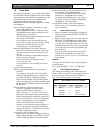
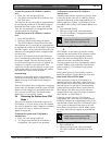
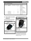
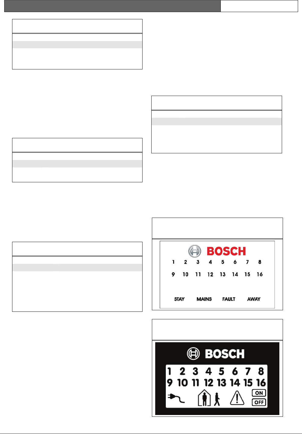
2.4 ICP-CP516 Sixteen Zone Codepads
The ICP-CP516 Sixteen Zone Codepad must be used
with sixteen wireless zone systems. The sixteen zone
codepads operation and display similarly to 8 zones
codepads, but also display zones 9 through 16.
Figure 4: ICP-CP516W Sixteen Zone LED
Codepad
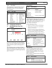
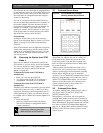
Figure 5: ICP-CP516LW Sixteen Zone LCD
Codepad