


ICP-CC488 | Installation Guide | 18.0 System and Consumer Options EN | 80
Bosch Security Systems, Inc. | 12/08 | F01U089457-02
For partitioned ICP-CC488 Control Panels, both
areas are automatically disarmed at the same time
each day.
17.14 Kiss-Off Wait Time
Location
490
Default
3
Increments of 500 ms (500 ms to 8 sec)
This location sets the time the control panel waits for
acknowledgment before resending a report. This
timer applies only to the 4 + 2 Express Format.
17.15 Speaker Beep Volume
Location
491
Default
13
0 No beeps
15 Loudest beeps
This location allows you to adjust the speaker volume
for remote radio operation.
17.16 System Time
Location
901 to 904
Location Default
Hour of the day (tens digit) 901 0
Hour of the day (units digit) 902 0
Minute of the day (tens digit) 903 0
Minute of the day (units digit) 904 0
The ICP-CC488 Control Panel has a real-time 24-
hour clock you must set during installation. Set this
time in 24-hour HHMM format (for example,
program 10:30 PM as 2230). You must reset the
System Time every time the system is powered
down.
17.17 System Date
Location
905 to 910
Location Default
Day of the month (tens digit) 905 0
Day of the month (units digit) 906 1
Month of the year (tens digit) 907 0
Month of the year (units digit) 908 1
Current year (tens digit) 909 0
Current year (units digit) 910 1
The ICP-CC488 Control Panel has a real-time
12-month calendar you must set during installation.
Set the date in DDMMYY format (for example,
program 1 January 2004 as 010104). You must reset
the System Date every time the system is powered
down.
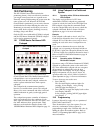
To set the date and time:
1. Enter your Master Code and press [6][AWAY].
Three beeps sound and the STAY and AWAY
indicators flash.
2. Enter the day, month, year, hour, and minute in
DD, MM, YY, HH, MM format (where DD is
the day of the month, MM is the month of the
year, YY is the year, HH is the hour of the day,
and MM minute of the day) and press [AWAY].
Use 24:00 hour format when programming the
hour of the day.
Two beeps sound and the STAY and AWAY
indicators are extinguished. If a long beep
sounds, there was an error when you entered the
date and time.
Example
To set the date and time for the 1st January 2004 at
10:30 PM, enter:
[2 5 8 0
6][AWAY][0
1 0 1 0
4 2
2
3
0][AWAY]
18.0 System and Consumer
Options
The locations in this section have up to four options.
You can select any combination of these options by
programming a single value. Calculate this value by
adding the option bit numbers together. Refer to
Section 7.3 Programming Option Bits on page 36 for
more information.
18.1 System Options 1
Location
492
1 Bosch Security Systems, Inc. smart lockout allowed
2 Horn speaker monitor
4 Strobe indications for radio arm/disarm
8
Assign Button 4 on transmitter to operate STAY
Mode 1
1 – Smart Lockout Allowed
This feature allows the control panel to remove any
zones that are programmed for lockout dialer from
the lockout list when the sirens are running. This
feature allows a monitoring station to receive zone
alarm reports from previously locked out zones
during siren time. Refer to Section 14.3.5 Zone Options
1 on page 61 for information on programming zones
for lockout dialer and lockout siren.
Refer to Section 14.5 Swinger Shutdown Count for Dialer
on page 64 to program the number of times the zone
can report before being locked out.
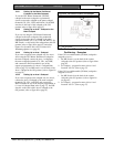
2 – Horn Speaker Monitor
If this option is selected, the control panel detects
when the horn speaker is disconnected from the
speaker terminals. The FAULT indicator lights when
the horn speaker is disconnected and is extinguished
when the horn speaker is reconnected.
If an output is required to operate when the horn
speaker is disconnected, use Output Event Type 1,6
Horn Speaker Monitor Fail (refer to page 72 for
more information).