


ICP-CC488 | Installation Guide | 16.0 Programmable Outputs EN | 76
Bosch Security Systems, Inc. | 12/08 | F01U089457-02
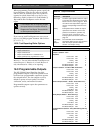
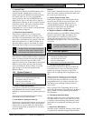
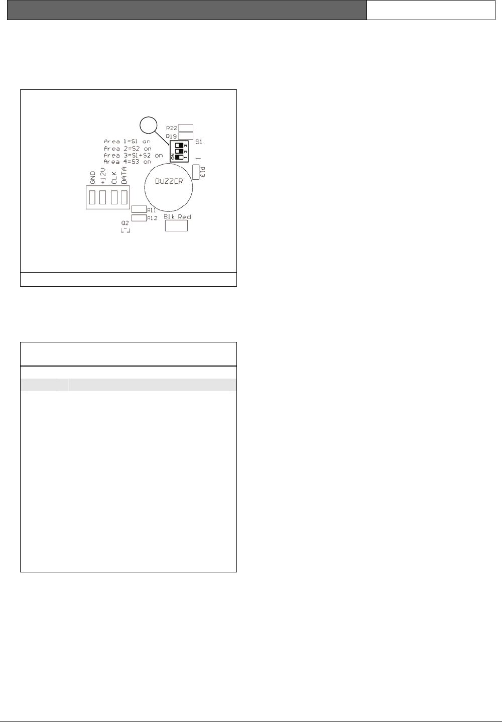
Set DIP Switch 2 to the ON position for the Area 2
codepad to operate correctly.
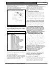
Refer to Figure 16 on page 76 for the location of the
DIP switches on the back of the codepad.
Figure 16: DIP Switch Location on Codepad
1
1 – DIP switches
16.3 Output Polarity
There are fifteen different polarities. Each polarity is
designated by a number that you program into the
appropriate location for the output.
Table 56: Event Type Polarities
Option Description
0 Output not used
1 Normally open, going low
2 Normally open, pulsing low
3 Normally open, one-shot low
4 Normally open, one-shot low (reactivate)
5 Normally open, one-shot low (can reset)
6 Normally open, one-shot low (alarm)
7 Normally open, latching low
8 Normally low, going open
9 Normally low, pulsing open
10 Normally low, one-shot open
11 Normally low, one-shot open (reactivate)
12 Normally low, one-shot open (can reset)
13 Normally low, one-shot open (alarm)
14 Normally low, latching open
0 – Output Not Used
If an output is not required, program the polarity as
0.
1 – Normally Open, Going Low
This polarity is normally open circuit and switches to
0 V when the event occurs. The output switches back
to open circuit when the event is restored. Time
parameters do not apply to this polarity.
2 – Normally Open, Pulsing Low
This polarity is normally open circuit and switches to
pulsing 0 V when the event occurs. The output
switches back to open circuit when the event is
restored. Time parameters vary the On time of the
pulse.
3 – Normally Open, One-Shot Low
This one-shot polarity is normally open circuit and
switches to 0 V when the event occurs. The output
switches back to open circuit when the time
parameter setting expires. This one-shot time setting
always runs its full duration and cannot be manually
reset.
4 – Normally Open, One-Shot Low with Reactivate
This one-shot polarity is normally open circuit and
switches to 0 V when the event occurs. Every time
the event occurs, it restarts the one-shot timer. The
output switches back to open circuit when the one-
shot time expires. This one-shot time setting always
runs its full duration. You cannot reset the time.
5 – Normally Open, One-Shot Low with Reset
This one-shot polarity is normally open circuit and
switches to 0 V when the event occurs. Because the
output switches back to open circuit when the one-
shot time expires or when the event returns to
normal, the operation of the output can be shortened
regardless of the programmed time parameter.
6 – Normally Open, One-Shot Low with Alarm
This one-shot polarity is normally open circuit and
switches to 0 V when the event occurs. The output
switches back to open circuit when the one-shot time
expires, the event returns to normal, or the system is
disarmed.
This polarity is ideally suited for the operation of
strobe lights because you can program the lights to
reset (up to 99 hours) and prevent them from burning
out or bothering others due to prolonged operation.
7 – Normally Open, Latching Low
This polarity is normally open circuit and switches to
0 V when the event occurs. The output switches back
to open circuit when a user holds down [7] on the
remote codepad until two beeps sound. Time
parameters do not apply to this polarity.
8 – Normally Low, Going Open
This polarity is normally 0 V and switches to open
circuit when the event occurs. The output switches
back to 0 V when the event is restored. Time
parameters do not apply to this polarity.
9 – Normally Low, Pulsing Open
This polarity is normally 0 V and switches to pulsing
open circuit when the event occurs. The output
switches back to 0 V when the event is restored.
Time parameters vary the Off time of the pulse.