


ICP-CC488 | Installation Guide | Contents EN | 6
Bosch Security Systems, Inc. | 12/08 | F01U089457-02
24.4
New Zealand Telepermit Notes................ 100
24.5 A-Tick........................................................... 101
25.0 Programming Sheets .................................. 101
25.1 ICP-CC488 Programming Sheets............. 101
26.0 Country Codes............................................ 110
Figures
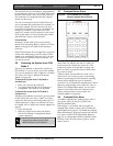
Figure 1: ICP-CP508W Eight Zone LED Codepad
..................................................................10
Figure 2: ICP-CP508LW Eight Zone LCD
Codepad ..................................................11
Figure 3: ICP-CP500PW Master Partitioned
Codepad ..................................................12
Figure 4: ICP-CP516W Sixteen Zone LED
Codepad ..................................................13
Figure 5: ICP-CP516LW Sixteen Zone LCD
Codepad ..................................................13
Figure 6: ICP-CP500PW LED Codepad Showing
Audible Alarm Buttons..........................16
Figure 7: RF3332: 2-Button Keyfob Transmitter 20
Figure 8: RF3334: 4-Button Keyfob Transmitter 20
Figure 9: Basic Pager Display................................47
Figure 10: Split EOL Resistors Using N/C Contacts
..................................................................57
Figure 11: Split EOL Resistors with Tamper Circuit
..................................................................57
Figure 12: Split EOL Resistors Using One N/O
Contact.....................................................57
Figure 13: Split EOL Resistors Using Two N/O
Contacts...................................................58
Figure 14: Wiring Diagram for Keyswitch Zone ..63
Figure 15: Wiring Diagram for Keyswitch Zone
Using Split EOL with Tamper .............63
Figure 16: DIP Switch Location on Codepad.......76
Figure 17: ICP-CP500PW Master Partitioned
Codepad ..................................................84
Figure 18: Area 1 Codepad Display.......................86
Figure 19: Area 2 Codepad Display.......................86
Figure 20: DIP Switch Location on Codepad.......87
Figure 21: Connections for CP-5 Master Partitioned
Codepad and CP-5 Area Addressable
Codepad ..................................................88
Figure 22: Connections for Two CP-5 Area
Addressable Codepads ..........................88
Figure 23: ICP-CC488 Wiring Diagram................95
Figure 24: ICP-CC488 Component Overlay ........96
Figure 25: DSRF Radio Receiver Wiring Diagram
..................................................................97
Figure 26: Telecom Connection Diagram for
Australia...................................................97
Figure 27: Telecom Connection Diagram for New
Zealand ....................................................98
Figure 28: Telecom Connection Diagram for China
...................................................................98
Tables
Table 1: Zone Defaults for the ICP-CC488..........9
Table 2: Zone Types..............................................10
Table 3: Zone Indicators .......................................10
Table 4: STAY Indicator.......................................10
Table 5: AWAY Indicator.....................................10
Table 6: MAINS Indicator....................................11
Table 7: FAULT indicator ....................................11
Table 8: Audible Indicators ..................................11
Table 9: MAINS Indicator....................................12
Table 10: Area On/Off Indicators .........................13
Table 11: Area Display Indicators .........................13
Table 12: AUX Indicator ........................................13
Table 13: PARTIAL Indicator................................13
Table 14: System FAULT indicators .....................19
Table 15: Fault Analysis Conditions......................20
Table 16: Horn Speaker Indication Beeps for
Remote Operations ................................21
Table 17: Strobe Indications for Remote
Operations ...............................................21
Table 18: Codepad Indicators for Remote Radio
User Numbers .........................................21
Table 19: Installer Code Functions........................22
Table 20: Domestic Dialing Digits.........................23
Table 21: Codepad Indicators When Changing
Phone Numbers ......................................24
Table 22: Telco Arm/Disarm Dialing Digits........24
Table 23: Telephone Monitor Mode Indications.26
Table 24: Event Sequence.......................................26
Table 25: Event Memory Playback .......................26
Table 26: Master Code Functions..........................27
Table 27: User Numbers Displayed by the
Codepad Indicators ................................28
Table 28: Remote Radio Numbers Displayed by
the Codepad Indicators..........................28
Table 29: Domestic Dialing Digits.........................29
Table 30: Codepad Indicators When Changing
Domestic Telephone Numbers.............29
Table 31: Telco Arm/Disarm Dialing Digits........29
Table 32: Event Sequence.......................................31
Table 33: Event Memory Playback .......................32
Table 34: Codepad Indicators ................................35
Table 35: Programming Option Bits Example.....36
Table 36: Installer’s Programming Mode
Commands...............................................36
Table 37: Command 965 Defaults.........................39
Table 38: Domestic Dialing Digits.........................43
Table 39: Contact ID Format Breakdown ............44