DSP 73
Xilinx Blocks
DDS
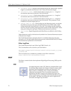
The Xilinx DDS Block implements a direct digital synthesizer (DDS),
also commonly called a numerically controlled oscillator (NCO). The
block employs a look-up table scheme to generate real or complex
valued sinusoids. An internal look-up table stores samples
representing one period of a sinusoid. A digital integrator
(accumulator) is then used to generate a suitable phase argument that
is mapped by the look-up table into the desired output waveform.
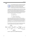
To understand how to use the DDS block, it is necessary to understand how the block
is implemented in hardware, as the block parameters are defined in terms of the DDS
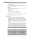
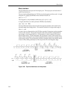
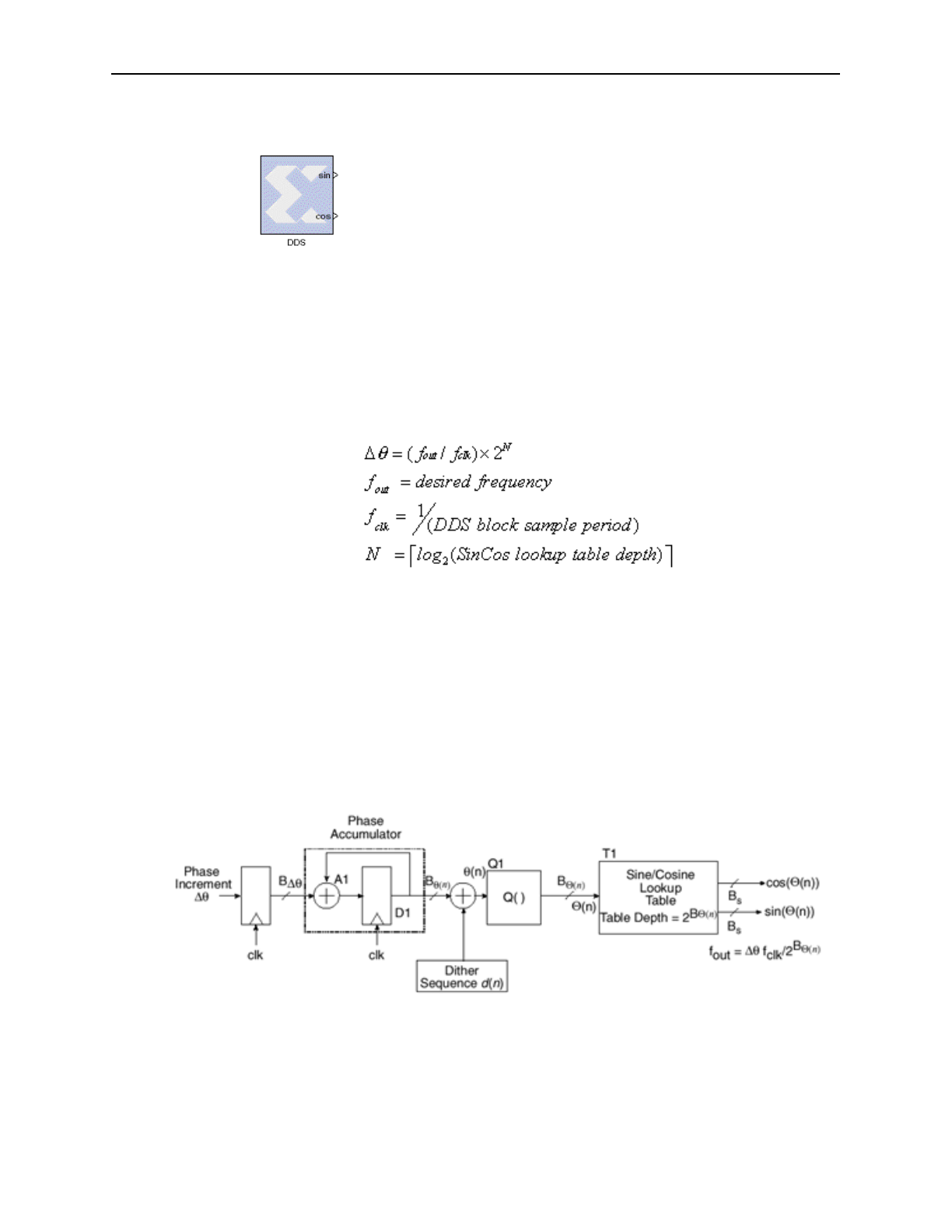
implementation as a Xilinx LogiCORE. The figure below shows a high-level view of
the core. The input phase increment ∆θ is registered and integrated in a phase
accumulator. A phase offset is added to the high-precision phase angle computed by
the accumulator, and the sum is quantized by truncation. The quantized value is then
used to index into the Sine/Cosine Lookup Table, mapping phase-space into time.
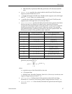
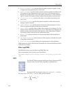
The phase increment ∆θ is defined by the following relationship
The phase offset and phase increment can be defined as constants or can be set
dynamically through optional input ports (details not shown in the figure). When one
or both are set dynamically, the block has a single data port, which is multiplexed
between the Phase Increment and Phase Offset inputs, with the selection determined
by the value on a select port of the block. If only one of the increment and offset is
configurable, there is no select port. The data value is registered in the Phase
Increment register or the Phase Offset register when the block’s write enable input is
1.
When phase dithering is used, the dither sequence d(n) linearises the quantizer Q()
that is used to produce the sine/cosine LUT address. The additional logic resources
required to implement the dither sequence generator are not significant.
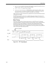
Figure 3-48: High-Level View of LogiCORE DDS Implementation


