


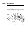


6-7
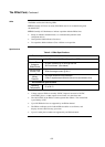
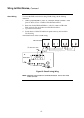
Table 6-2 Cable Run Lengths
1. The current allowance per device on the loop is 0.5mA with the LED off, 2mA with
the LED on. A maximum of 20 LEDs will be turned on at any time by the IDNet
Card, e.g. in alarm.
2. The minimum voltage allowed at the furthest device to guarantee operation is
24.9Vdc. The IDNet boosts its output voltage from 30V to 35V during alarm.
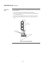
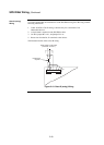
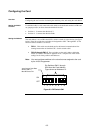
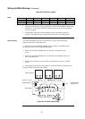
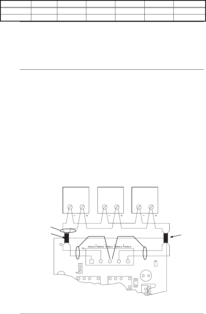
To connect the IDNet card to devices using Class A wiring, read the following
instructions and refer to the figure below.
1. Route wire from the IDNetB+, IDNetB- outputs on TB1 of the IDNet card to
the appropriate inputs on a peripheral IDNet device.
2. Route wire from the first IDNet device to the next one. Repeat for each
device.
3. Route wire from the last IDNet device to the IDNetA+ and IDNetA- inputs on
TB1 of the IDNet card.
4. Separate every 40 devices (at most) with a communications isolator, e.g. 4090-
9116.
5. Separate the power feed to sounder bases or 6 point I/O modules in different zones
using the 4090-9117 Power Isolate module.
+
1
2
1 212
Figure 6-4. Class A (loop) Wiring
Continued on next page
Wiring to IDNet Devices, Continued
Wire Size 0.75 mm
2
1 mm
2
1.5 mm
2
2.5 mm
2
4 mm
2
Resistance
Distance 385 m 513 m 769 m 1,282 m 2,052 m
20Ω
Distance 769 m 1,026 m 1,538 m 2,565 m 4,104 m
40Ω
Notes
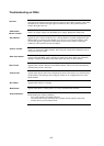
Class A Wiring
IDNET CARD
IDNET DEVICES
0.75 mm
2
to 4 mm
2
SHIELD
SHIELD
FERRITE BEAD
FERRITE BEAD
(see figure 5.1)