


C-1
This appendix contains instructions on how to use a volt/ohm meter to check system
wiring.
When using the volt/ohm meter to check each circuit, make sure to adhere to the notes
and instructions below.
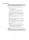
Notes:
• Ensure that no power is applied to the 4100U-S1 fire alarm panel
and that all wiring is properly connected (terminal blocks,
LED/switch module ribbon cables, etc.).
• Use the earth stud in the control panel for all measurements to
ground.
• Each circuit must test free of all grounds and extraneous voltages.
Use the volt/ohm meter as described in the steps below to check each
circuit type.
1. At the control panel, locate wires from each initiating device
or indicating appliance circuit.
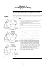
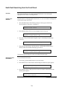
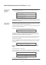
2. Check each circuit for extraneous voltage by setting the
volt/ohm meter to 300VAC. Place the meter probes so that
the black probe is on the “-” wire and the red probe is on the
“+” wire. Meter readings must show 0 volts (see Figure C-
1A).
3. Set the volt/ohm meter to 60 VDC and repeat step 2. The
meter must read 0 volts (see Figure C-1A).
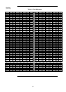
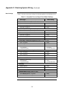
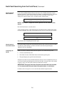
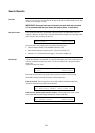
4. Set the volt/ohm meter to OHMS x 10 and place the meter
probes as described in step 2. Check the circuits using the
resistance measurements in Table C-1. Locate and correct
any abnormal conditions at this time. Note: If the reading
indicates an open circuit in an initiating circuit, make sure the
smoke detector heads are properly mounted and seated. The
circuit may be open if smoke detector power is not present,
and if separately powered 4-wire devices are used.
5. Check all other system wiring to verify that each circuit is
free of grounds and extraneous voltages.
Continued on next page
Appendix C
Checking System Wiring
Overview
Using the Volt/
Ohm Meter
A. No Voltage
B. Open Circuit
C. Short Circuit
Figure C-1. Volt/Ohm Meter Readings