


xi
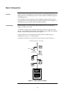
Figure 1-1. Basic 4100U-S1 System............................................................................... 1-2
Figure 2-1. CPU Motherboard (566-227) ....................................................................... 2-3
Figure 2-2. CPU Card (566-149) .................................................................................... 2-4
Figure 2-3. Operator Interface........................................................................................ 2-6
Figure 2-4. System Power Supply.................................................................................. 2-7
Figure 2-5. The Power Distribution Interface (PDI)......................................................... 2-8
Figure 2-6. Power and Communication Wiring for Motherboards (note that there
are limitations of where motherboards can be placed – see next section)............
2-12
Figure 2-7. Expansion Bay 4”x 5” Card Placement...................................................... 2-13
Figure 2-8. Expansion Bay Motherboard Placement ................................................... 2-14
Figure 2-9. Slave Card/PDI Connection........................................................................ 2-15
Figure 2-10. Installing the Motherboard in a 4100U-S1 Expansion Bay....................... 2-16
Figure 2-11. LED/Switch Modules................................................................................. 2-18
Figure 2-12. LED/Switch Controller............................................................................... 2-18
Figure 2-13. LED/Switch Card Mounting....................................................................... 2-19
Figure 2-14. Controller Card Mounting.......................................................................... 2-20
Figure 2-15. LED/Switch Controller Wiring (approximately as viewed on the rear
of the open bay door) .............................................................................................
2-21
Figure 2-16. ME0456 Fan Control Module.................................................................... 2-23
Figure 3-1. Ring/Star Configuration Example................................................................. 3-2
Figure 3-2. Interconnected Loop Configuration.............................................................. 3-3
Figure 3-3. 4100-6014 Network Interface Card............................................................... 3-5
Figure 3-4. The 4100-6057 Fiber-Optic Media Card ....................................................... 3-6
Figure 3-5. The 4100-6056 Wired Media Card................................................................ 3-6
Figure 3-6. Media Card Mounting.................................................................................... 3-9
Figure 3-7. Coupler Wiring ............................................................................................ 3-14
Figure 3-8. Wired Media Interconnection between CPU Motherboards in different
panels.....................................................................................................................
3-15
Figure 3-9. Example of Ring/Loop NetworkWiring ........................................................ 3-16
Figure 4-1. The Alarm Relay Card .................................................................................. 4-7
Figure 5-1. The Ferrite Bead ........................................................................................... 5-2
Figure 5-2. Class A (loop) NAC Wiring............................................................................ 5-4
Figure 5-3. Class B (string) Wiring .................................................................................. 5-5
Figure 5-4. Relay Module Connection to a T-Gen 50 ..................................................... 5-9
Figure 5-5. NAC Connection to a T-Gen 50.................................................................. 5-11
Figure 5-6. Wiring an Evacuation Controller to a T-Gen 50.......................................... 5-13
Figure 5-7. Examples of Evacuation Controls and PA Microphone .............................. 5-14
Figure 5-8. Auxiliary Power Wiring................................................................................ 5-16
Figure 5-9. Class A (loop) Wiring .................................................................................. 5-19
Figure 5-10. Class B (string) Wiring .............................................................................. 5-20
Figure 6-1. The IDNet Card............................................................................................. 6-2
Figure 6-2. Mounting onto the Power Distribution Interface in the Expansion Bay......... 6-4
Figure 6-3. DIP Switch SW1............................................................................................ 6-5
Figure 6-4. Class A (loop) Wiring .................................................................................... 6-7
Figure 6-5. Class B (string) Wiring .................................................................................. 6-8
Figure 7-1. Service and Diagnostic Interface .................................................................. 7-2
Figure 7-2. Data Transfer Interface ................................................................................. 7-2
Figure 7-3. Bootloader Interface...................................................................................... 7-3
Figure C-1. Volt/Ohm Meter Readings ............................................................................C-1
List of Figures