


2-13
This section contains guidelines and instructions on installing 4”x 5” cards and traditional
motherboards into the 4100U-S1 expansion bay.
IMPORTANT: This section applies to aftermarket modules for expansion bays only. If
you do not need to install any aftermarket modules at all, you have
completed the panel installation and can apply AC power.
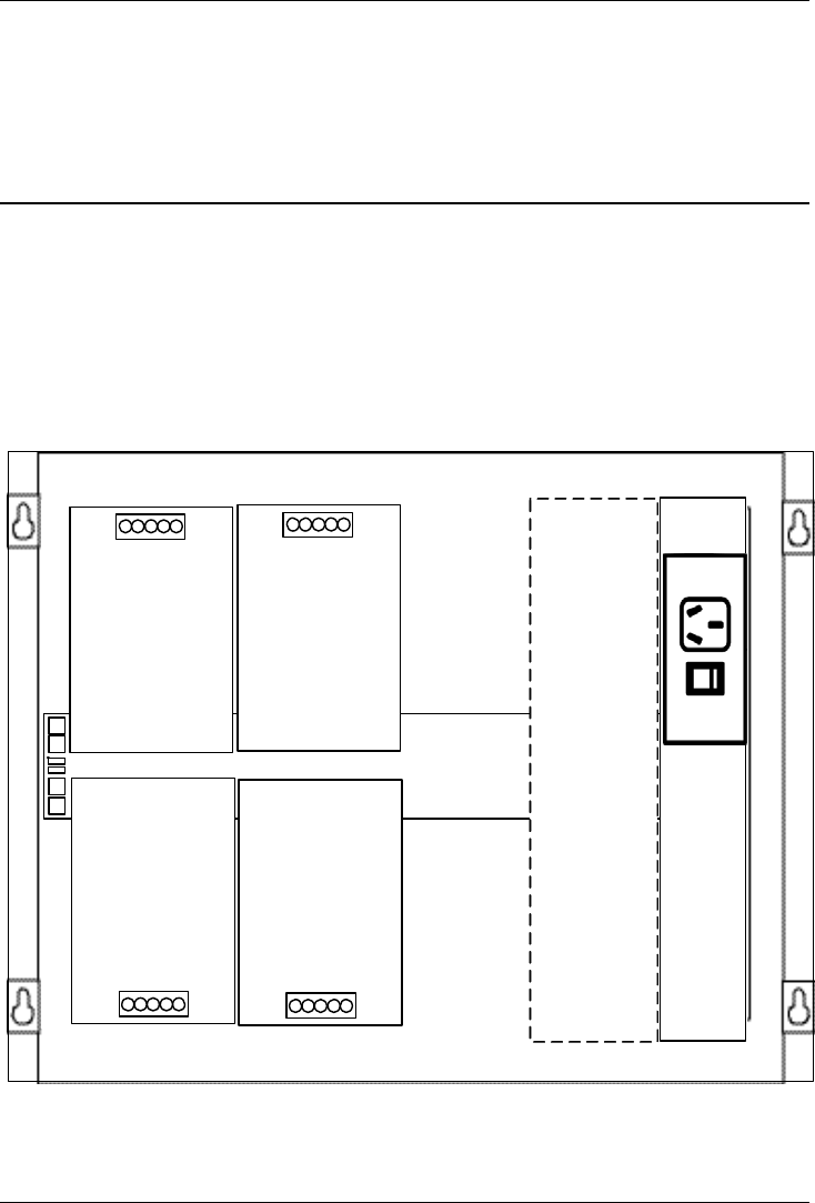
Refer to the following guidelines before mounting 4” x 5” cards and/or motherboards to
the expansion bay.
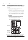
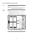
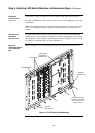
• The expansion bay assembly includes a chassis, two end supports, one LED/switch
frame, and a power distribution interface (PDI) board.
• An expansion bay holds up to four 4” x 5” modules if a T-Gen 50 is fitted, or up to
six modules if not.
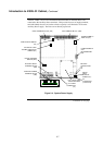
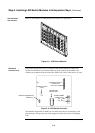
Figure 2-7. Expansion Bay 4”x 5” Card Placement
Continued on next page
Step 5. Installing Modules into Expansion Bays
Overview
Placement
Guidelines
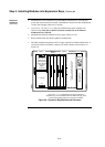
Power Distribution Interface (PDI)
I/O Wiring
4" x 5" Module
Block A Block C Block E
Block B Block D Block F
Slots 7 & 8
I/O Wiring
4" x 5" Module
I/O Wiring
4" x 5" Module
I/O Wiring
4" x 5" Module
Main Outlet (GPO)
Mounting Bracket
T-Gen 50 on mounting bracket (if fitted)
(heatsink intrudes into slot 6 space)