


2-10
Note: Some devices that connect to RUI have inherently grounded shield
terminals, in which case 24 C cannot be used. If 24 C is used, a Negative
Ground Fault will occur.
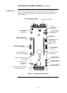
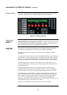
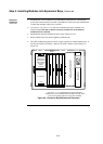
P10/P11: P10 is associated with Port 1 and P11 is associated with Port 2. P10 and P11 are
used to set the CPU motherboard up to be attached to either a network card or a RS-
232/2120 card.
• Position 1 – 2: Network card (NIC) plugged into CPU motherboard (default).
• Position 2 – 3: RS-232/2120 card plugged into CPU motherboard.
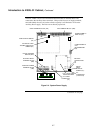
The CPU daughter card must be jumpered as follows:
P1 is used for engineering diagnostics (COMLAB). Normally has no link fitted.
• Position 1 – 2 : Download or no connection.
• Position 2 – 3 : Diagnostic mode.
P3 configures the RAM battery as ON or OFF.
• Position 1 – 2 : ON – move to this position for normal operation.
• Position 2 – 3 : OFF – factory setting.
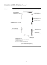
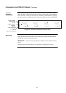
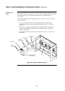
The SPS must be configured as follows:
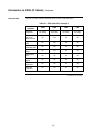
SW1: Using DIP switch SW1, set the SPS card address to 1. Use the address table in
Appendix A for the switch settings.
P2: P2 configures the IDNet shield connection.
• Position 1 – 2 (bottom) : Connects the shield to 0 V (default). Use this setting for
4100U-S1.
• Position 2 – 3 (top) : Connects the shield to earth ground.
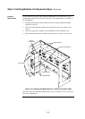
P3 configures relay 3 on the 4100-6033 Alarm Relay Card.
• Position 1 – 2 (top) : Removes fault monitoring on Relay 3 (default). Use this setting
for 4100U-S1.
• Position 2 – 3 (bottom) : Makes Relay 3 activate when there is a fault.
P1: Earth connect jumper.
• Position 1 – 2 (rhs): Enables Earth fault monitoring. Set to this position unless the
system uses a TrueAlert Power Supply under common 0 V. Use this setting for
4100U-S1.
• Position 2 – 3 (lhs): Disables Earth fault monitoring. Set to this position only if the
system uses a TrueAlert Power Supply under common 0 V.
P4/P5: The PDI can be configured to draw its power from different sources via P4 and
P5. For 4100U-S1 both links should be in position 1-2.
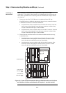
Refer to the appropriate installation instructions to configure other cards that are located
in the CPU and expansion bays. The common 4100U cards and modules are included in
this manual. Refer to Appendix D for a list of publications.
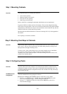
Step 3. Configuring Cards, Continued
CPU Daughter Card
Configuration
SPS Configuration
PDI Configuration
Configuring Other
Cards