


3-10
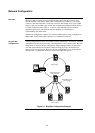
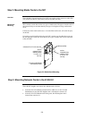
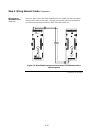
The nodes in the network now have to be wired together, so that the NIC in one host
panel connects to the NIC in the next panel.
Refer to the following guidelines field wiring
General
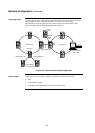
• Network nodes must be wired from right port to left port, regardless of the media
type selected.
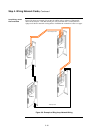
• Best protection is achieved by wiring the nodes in a loop fashion. A single fault
(except an Earth fault) will cause the network to reconfigure for degraded
operation. A second fault (except an Earth fault) will result in the network
dividing into two separate networks.
• It is permissible to use mixed media in a network. For example, some spans may
be wired media while others are optical fiber.
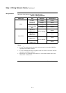
• Each NIC has a jumper for selecting between network data rates of 57.6 kbps
and 9.6 kbps. All cards in the network must be set for the same rate. When
physical bridging is used, the data rate must be set to 9.6kbps.
• Each NIC has a jumper for selecting between 8- and 9-bit network protocols. All
cards in the network must be set for the same network protocol. When physical
bridging is used, the protocol must be set to 9-bit.
Wired Media
• Earth fault detection is performed on the left port only. When a network Earth
fault occurs, the trouble is reported on the node whose left port is connected to
the earthed section.
• All 0.8mm
2
wiring used Wired Media Cards must be shielded twisted-pair. All
0.2mm
2
(telephone cable) used must be twisted pair. When shielded cable is
used, the shield must be terminated to chassis Earth on the left port only.
• All network wiring except the shield is supervised and power limited.
• When wiring leaves the building, 2081-9044 Overvoltage Protectors should be
connected at the entry point. One overvoltage protector is installed where wiring
leaves the building; another is installed where wiring enters the next building.
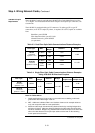
Fiberoptic
• All fibre cables must be multimode, graded index type. ST style connectors must be
used. No physical strain should be put on the cables. There must be no cable bends
of less than a 50mm radius.
• Two methods are available for joining fibre cable. Splices provide a permanent, very
low loss, fibre-to-fibre connection. Couplers provide temporary connection between
two ST style connectors with a loss of 1.2dB. Both methods are permitted on a fibre
network.
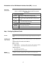
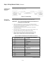
• Maximum line lengths for 50/125 and 62.5/125 cable are shown in
Table 3-2.
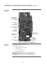
Step 4. Wiring Network Cards
Overview
Wiring Guidelines