


2-20
Refer to the figures and instructions below to mount the LED/switch controller card
assembly to the back of one of the LED/switch cards.
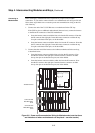
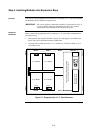
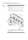
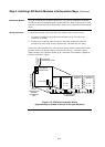
1. Use four 322-123 Nuts and four 268-009 bay Washers to secure the 637-141
Bracket to the inside front of the expansion bay. Note that there is only one
location where the bracket can be mounted, as shown in Figure 2-13.
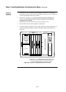
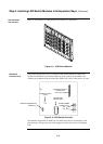
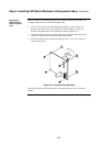
2. Attach the header connector on the back side of the controller (P4) to the P1 (In)
connector on the back side of the first LED/switch modules.
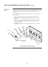
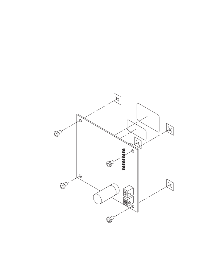
3. Secure the controller card to the board using four 6/32” x 1/4 “ Torx screws, as
shown in Figure 2-14.
Figure 2-14. Controller Card Mounting
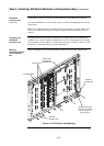
The second Controller Card (4100-1289) is mounted in the spare space on the same
bracket.
Continued on next page
Step 6. Installing LED/Switch Modules into Expansion Bays, Continued
Mounting the
Additional LED/
Switch Controller
Card