


6-3
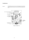
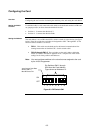
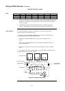
The IDNet card has the following LEDs:
LED1. Normally off. Turns on steady if the IDNet card is not communicating with
the 4100U CPU.
LED2. Normally off. Illuminates to indicate a problem with the IDNet lines.
• Steady on indicates channel failure, i.e. communication problems with
configured devices.
• One repetitive blink indicates a line short.
• Two repetitive blinks indicate a Class A failure or an open line.
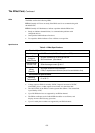
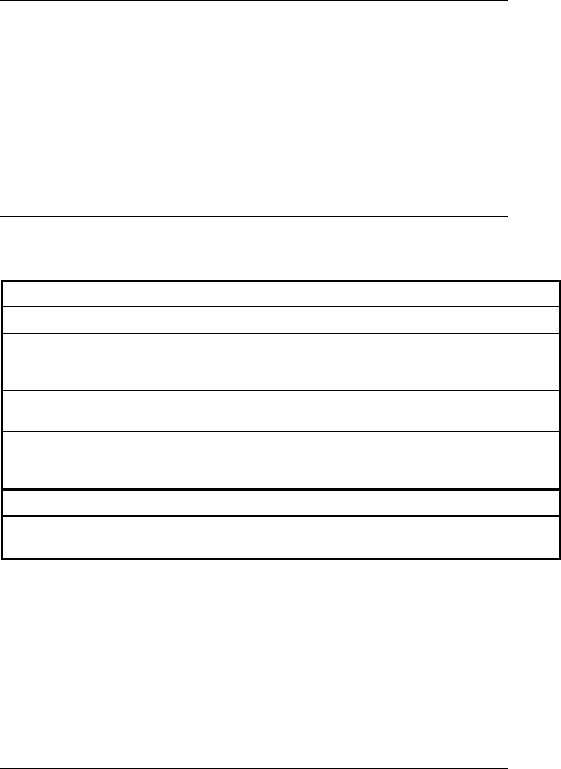
Table 6-1. IDNet Specifications
Electrical Specifications
Input Voltage 24 VDC nominal (24V Card Supply from SPS)
Comms/Power
Voltage to
IDNet Slaves
30 VDC (nominal) or 35 VDC @ 250 mA
36.5V maximum (See below)
Comms/Power
Current Limit
350mA average current @ 49° C
Comms/Power
Wiring
Distance
40 Ohms maximum loop resistance
0.58 μF capacitance maximum (line to line and shield to line)
Environmental Specifications
Operating
Temperature
0° to 50° C
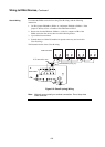
• Voltage output to IDNet is normally 30VDC. Output is increased to 35VDC
when LEDs, piezos, or other outputs are activated, as in the alarm state.
• The 30/35V PSU on the IDNet is rated at greater than 350mA. The current limit
is provided by a PTC.
• Up to 250 IDNet devices are supported by one IDNet channel.
• The IDNet card keeps track of which LEDs should be on at all times, and
displays no more than 20 at any given time.
• Up to 43 coded piezo sounders are supported by one IDNet channel.
The IDNet Card, Continued
LEDs
Specifications