


6-6
Up to 250 IDNet slave devices, such as smoke detectors and manual call points, can be
connected to the IDNet card using Class A (loop) or Class B (line) wiring, with the
following restrictions.
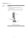
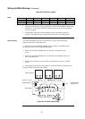
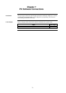
Class A wiring allows the devices to communicate with the IDNet card even in the event
of an open circuit somewhere in the loop. Class A wiring requires that two wires are
routed from the IDNet card to each IDNet device, and then back again to the IDNet card.
Under AS1670.1 every group of 40 devices (or less) must be separated by a Comms
Isolator.
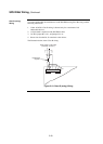
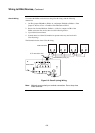
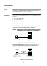
Class B wiring allows “T” tapping, and therefore requires less wiring distance per
installation than Class A. IDNet wiring does not require end-of-line resistors, because
each IDNet device communicates directly to the IDNet card. A maximum of 40 devices
is allowed to be connected with Class B wiring.
See Appendix F for a list of compatible devices and their ratings.
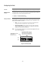
• Use ferrite beads on wiring. See Figure 5.1.
• Shielded cable is recommended in electrically noisy environments.
• IDNet cabling should not be run adjacent to other cabling, especially non-fire
system cabling, such as mains.
• The limiting factors on the length of the twin core cable connecting the IDNet
devices to the IDNet card are cable capacitance (attenuates the superimposed
coms signal) and resistance (causes voltage drop of the supply voltage and
comms signals).
• The maximum capacitance of 0.58uF core to core must also include the mutual
capacitance of core to earth. The latter is greatly increased when shielded cable
is used.
• Rather than do voltage drop calculations, the following simplified rules can be
applied.
• 125 devices or less: allow a maximum of 40Ω to any device (Class B), and
in any loop (Class A).
• 250 devices: allow a maximum of 20Ω in any loop.
• 125 to 250 devices: linear de-rating between 40Ω and 20Ω can be applied.
Calculate R
L
= 20Ω x (1 + (250-n)/125) where R
L
is the allowable line
resistance and n is the number of devices used.
Example: for 200 devices the maximum resistance allowed may be extended
from 20Ω to: 20Ω + 20Ω x (250 – 200) / 125 = 28Ω
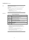
• Use the resistance specifications that apply to the cable being used. The values
used in this manual allow 39Ω per km for 2 core of 1 mm
2
for copper wire at
49°C. (A commonly used value is 34Ω per km for 2 core of 1 mm
2
at 20°C).
See Table 6.2. Note that this includes both cores.
• Sounder bases and 6 point I/O modules do not draw the alarm load from the
loop, but are powered from separate 24V terminals.
• Where devices, e.g. sounder bases, are wired from a 24V source (e.g. supplied
by 24V Aux Power or a NAC), and are in more than 1 zone, the power cable
must also be isolated between zones by a 4090-9117AU Power Isolator Module.
Continued on next page
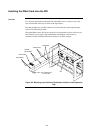
Wiring to IDNet Devices
Overview
Guidelines