


Teledyne API – Technical Manual - Model 300E Family CO Analyzers Troubleshooting & Repair
303
13.6.3.2. Adjusting the Sync/Demodulator, Circuit Gain
To adjust the sync/demodulator circuit gain:
1. Make sure that the analyzer is turned on and warmed up.
2. Set the analyzer display to show the STABIL or CO STB test function.
3. Apply Zero Air to Sample Inlet of the analyzer.
4. Wait until the stability reading falls below 1.0 ppm.
5. Change the analyzer display to show the CO MEAS.
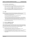
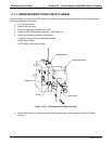
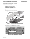
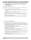
6. Remove the Sync/Demod Housing
Remove the two mounting screws.
Carefully lift the housing to reveal the sync/demod PCA.
Sync/Demod
PCA Housing
Housing Mounting
Screws
Optical Bench
Figure 13-19: Location of Sync/Demod Housing Mounting Screws
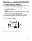
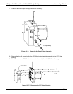
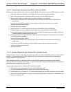
7. Adjust potentiometer VR1 until CO MEAS reads 4500 mV ± 300 mV
V
R1
Adjustment Made Here
Figure 13-20: Location of Sync/Demod Gain Potentiometer
04288D DCN5752