


Advanced Features Teledyne API – Technical Manual - Model 300E Family CO Analyzers
144
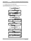
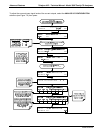
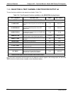
7.4.6. SELECTING A TEST CHANNEL FUNCTION FOR OUTPUT A4
The test functions available to be reported are listed in Table 7-10:
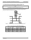
Table 7-10: Test Channels Functions available on the M300E/EM’s Analog Output
TEST CHANNEL DESCRIPTION ZERO
FULL SCALE
*
NONE TEST CHANNEL IS TURNED OFF.
CO MEASURE
The demodulated, peak IR detector output
during the measure portion of the GFC Wheel
cycle.
0 mV 5000 mV
CO REFERENCE
The demodulated, peak IR detector output
during the reference portion of the GFC
Wheel cycle.
0 mV 5000 mV
SAMPLE PRESS
The absolute pressure of the Sample gas as
measured by a pressure sensor located inside
the sample chamber.
0" Hg 40 "Hg
SAMPLE FLOW
Sample mass flow rate as measured by the
flow rate sensor in the sample gas stream.
0 cm
3
/m 1000 cm
3
/m
SAMPLE TEMP
The temperature of the gas inside the sample
chamber.
0C 70C
BENCH TEMP
Optical bench temperature.
0C 70C
WHEEL TEMP
GFC Wheel temperature.
0C 70C
O
2
CELL TEMP
The current temperature of the O
2
sensor
measurement cell.
n
70C
CHASSIS TEMP
The temperature inside the analyzer chassis.
0C 70C
PHT DRIVE
The drive voltage being supplied to the
thermoelectric coolers of the IR photo-
detector by the Sync/Demod Board.
0 mV 5000 mV
* Maximum test signal value at full scale of test channel output.
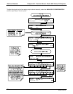
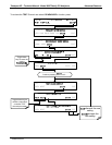
Once a function is selected, the instrument not only begins to output a signal on the analog output, but also adds
TEST to the list of test functions viewable via the front panel display.
04288D DCN5752