


Teledyne API – Technical Manual - Model 300E Family CO Analyzers Troubleshooting & Repair
293
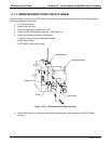
13.5.6.6. Pressure/Flow Sensor Assembly
The pressure/flow sensor PCA, located on the top of the absorption bench, can be checked with a voltmeter
using the following procedure which, assumes that the wiring is intact, and that the motherboard and the power
supplies are operating properly:
1. For Pressure related problems:
Measure the voltage across C1 it should be 5 ± 0.25 VDC.
If not then the board is bad.
Measure the voltage across TP4 and TP1.
With the sample pump disabled it should be 4500 mV ±250 mV.
With the pump energized it should be approximately 200 mV less. If not, then S1, the pressure
transducer is bad, the board is bad, or there is a pneumatic failure preventing the pressure
transducer from sensing the absorption cell pressure properly.
2. For flow related problems:
Measure the voltage across TP2 and TP1 it should be 10 ±0.25 VDC.
If not then the board is bad.
Measure the voltage across TP3 and TP1.
With proper flow (800 sccm at the sample inlet) this should be approximately 4.5V (this voltage
will vary with altitude).
With flow stopped (sample inlet blocked) the voltage should be approximately 1V.
If the voltage is incorrect, the flow sensor is bad, the board is bad or there is a leak upstream of
the sensor.
04288D DCN5752