


Teledyne API – Technical Manual - Model 300E Family CO Analyzers Remote Operation
149
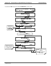
8. REMOTE OPERATION
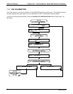
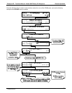
8.1. SETUP MORE COMM: USING THE ANALYSER’S
COMMUNICATION PORTS
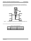
The M300E/EM is equipped with two serial communication ports located on the rear panel (see Figure 3-2).
Both ports operate similarly and give the user the ability to communicate with, issue commands to, and receive
data from the analyzer through an external computer system or terminal. By default, both ports operate on the
RS-232 protocol.
The RS232 port can also be configured to operate in single or RS-232 multidrop mode (option 62; See
Section 5.7.2 and 8.2).
The COM2 p
ort can
be configured for standard RS-232 operation, half-duplex RS-485 communication or
for access via an LAN by installing the Teledyne API’s Ethernet interface card (option 63; See Section
5.7.3 and 8.4).
A Code
-Activated Switch
(CAS), can also be used on either port to connect typically between 2 and 16
send/receive instruments (host computer(s) printers, data loggers, analyzers, monitors, calibrators, etc.) into one
communications hub. Contact Teledyne API sales for more information on CAS systems.
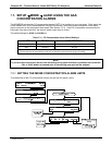
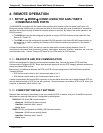
8.1.1. RS-232 DTE AND DCE COMMUNICATION
RS-232 was developed for allowing communications between Data Terminal Equipment (DTE) and Data
Communication Equipment (DCE). Basic data terminals always fall into the DTE category whereas modems are
always considered DCE devices.
Electronically, the difference between the DCE and DTE is the pin assignment of the Data Receive and Data
Transmit functions.
DTE devices receive data on pin 2 and transmit data on pin 3.
DCE devices receive data on pin 3 and transmit data on pin 2.
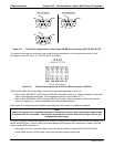
A switch located below the bottom DB-9 connector on the rear panel allows the user to switch between DTE (for
use with data terminals) or DCE (for use with modems). Since computers can be either DTE or DCE, check your
computer to determine which mode to use.
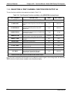
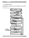
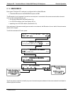
8.1.2. COMM PORT DEFAULT SETTINGS
Received from the factory, the analyzer is set up to emulate a DCE or modem, with pin 3 of the DB-9 connector
designated for receiving data and pin 2 designated for sending data.
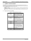
RS-232 RS-232 (fixed) DB-9 male connector.
Baud rate: 19200 bits per second (baud).
Data Bits: 8 data bits with 1 stop bit.
Parity: None.
COM2: RS-232 (configurable to RS 485), DB-9 female connector.
Baud rate:115000 bits per second (baud).
Data Bits: 8 data bits with 1 stop bit.
Parity: None.
04288D DCN5752