


Troubleshooting & Repair Teledyne API – Technical Manual - Model 300E Family CO Analyzers
278
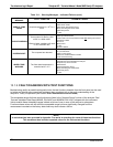
13.2. GAS FLOW PROBLEMS
When troubleshooting flow problems, it is a good idea to first confirm that the actual flow and not the analyzer’s
flow sensor and software are in error, or the flow meter is in error. Use an independent flow meter to perform a
flow check as described in Section 12.3.4. If this test shows the flow to be co
rre
ct, check the pressure sensors
as described in Section 13.5.6.6.
The M300
E/EM has one main gas flow path. With the IZS or zero/span valve option installed, there are several
subsidiary paths but none of those are displayed on the front panel or stored by the iDAS.
With the O
2
sensor option installed, third gas flow controlled with a critical flow orifice is added, but this flow is not
measured or reported.
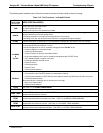
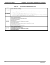
In general, flow problems can be divided into three categories:
1. Flow is too high
2. Flow is greater than zero, but is too low, and/or unstable
3. Flow is zero (no flow)
When troubleshooting flow problems, it is crucial to confirm the actual flow rate without relying on the analyzer’s
flow display. The use of an independent, external flow meter to perform a flow check as described in Section
12.3.4 is essential.
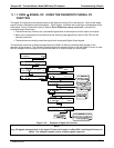
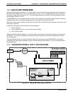
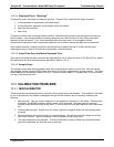
The flow diag
rams found in a variety of locations within this manual depicting the M300E/EM in its standard
configuration and with options installed can help in trouble-shooting flow problems. For your convenience they
are collected here.
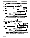
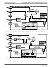
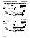
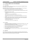
13.2.1. M300E/EM INTERNAL GAS FLOW DIAGRAMS
Figure 13-6: M300E/EM – Basic Internal Gas Flow
04288D DCN5752