


Remote Operation Teledyne API – Technical Manual - Model 300E Family CO Analyzers
160
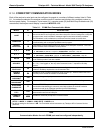
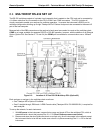
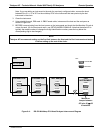
8.2. MULTIDROP RS-232 SET UP
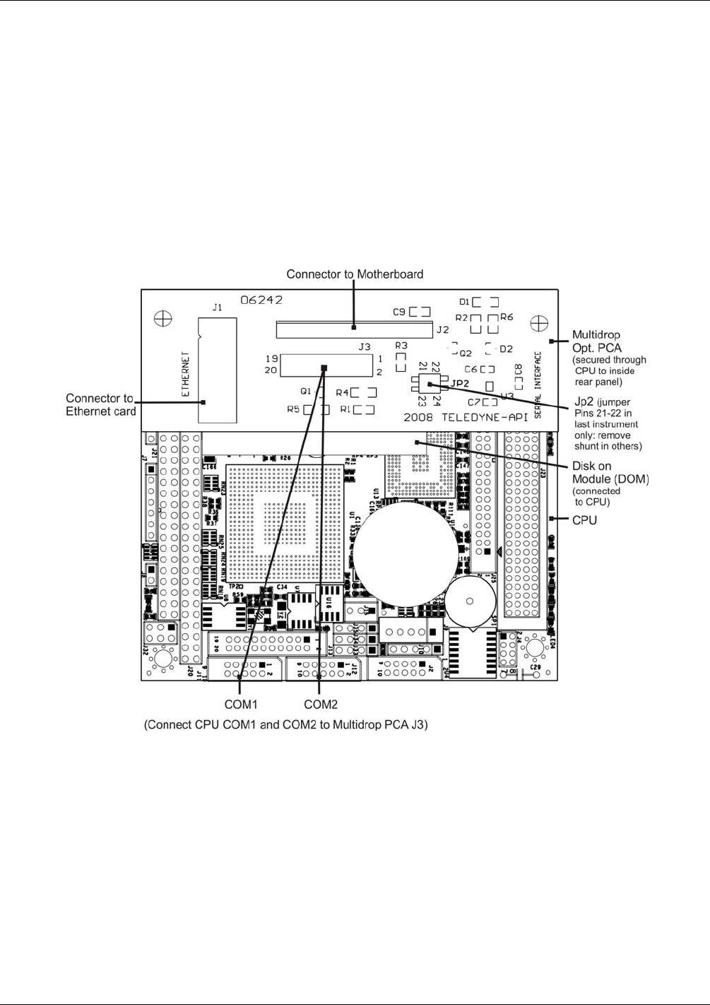
The RS-232 multidrop consists of a printed circuit assembly that is seated on the CPU card and is connected by
a Y-ribbon cable from its J3 connector to the CPU’s COM1 and COM2 connectors. This PCA includes all
circuitry required to enable your analyzer for multidrop operation. It converts the instrument’s RS232 port to
multidrop configuration allowing up to eight Teledyne API’s E-Series Analyzers to be connected to the same I/O
port of the host computer.
Because both of the DB9 connectors on the analyzer’s back panel are needed to construct the multidrop chain,
COM2 is no longer available for separate RS-232 or RS-485 operation; however, with the addition of an Ethernet
Option (Option 63A, See Section 5.7.3 and 8.4) the COM2 po
rt is a
vailable for communication over a 10BaseT
LAN.
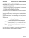
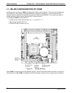
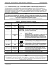
Figure 8-3: Location of JP2 on RS-232-Multidrop PCA (Option 62)
Each analyzer or analyzer in the multidrop chain must have:
One Teledyne API’s Option 62 installed.
One 6’ straight-through, DB9 male DB9 Female cable (Teledyne API’s P/N WR0000101) is required for
each analyzer.
To set up the network, for each instrument:
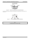
1. With NO power to the instrument, remove its top cover and locate JP2 on the multidrop PCA, which is
assembled with a shunt that jumpers Pins 21 22 (Error! Reference source not found.).
2. Remove and store the shunt (place the shunt on one pin only) for all instruments in the network except
the instrument that is to be the last: make sure a shunt is in place connecting Pins 21 22 for the last
instrument.
04288D DCN5752