


Getting Started Model GFC7000TA Carbon Dioxide Analyzer
Teledyne Analytical Instruments 26
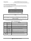
3.6.1. Basic Pneumatic Connections
NOTE
In order to prevent dust from getting into the gas flow channels of your analyzer,
it was shipped with small plugs inserted into each of the pneumatic fittings on the
back panel. Remove these plugs before operating the analyzer. It is recommended
that they be stored for future use (moving, storing or shipping the analyzer).
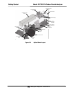
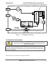
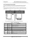
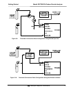
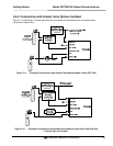
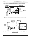
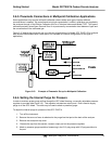
Figure 3-4 illustrates the basic configuration for gas supply and exhaust lines to the Model GFC 7000TA
Analyzer. Figure 3-5 illustrates the internal gas flow of the instrument in its basic configuration.
Please refer to Figure 3-2 for pneumatic connections at the rear panel and Table 3-2 for description.
NOTE
Sample and calibration gases should only come into contact with PTFE (Teflon),
FEP, glass, stainless steel or brass.
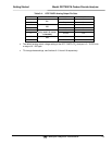
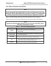
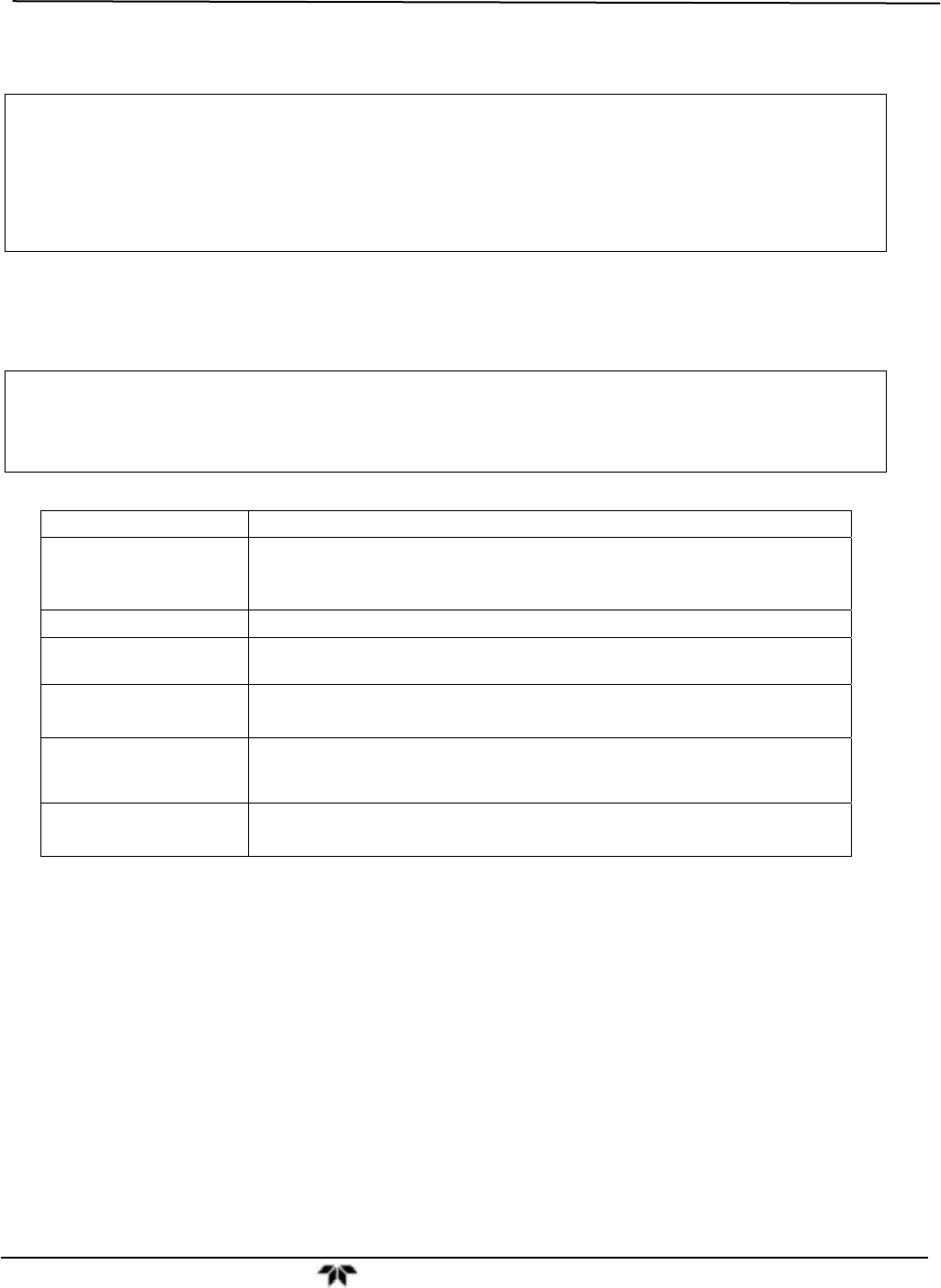
Table 3-7: Rear Panel Pneumatic Connections
REAR PANEL LABEL FUNCTION
SAMPLE
Connect a gas line from the source of sample gas here.
Calibration gasses are also inlet here on units without zero/span valve or IZS
options installed.
EXHAUST
Connect an exhaust gas line of not more than 10 meters long here.
PRESSURE SPAN
On units with zero/span valve options installed, connect a gas line to the source
of calibrated span gas here.
VENT SPAN
Span gas vent outlet for units with zero/span valve options installed.
Connect an exhaust gas line of not more than 10 meters long here.
IZS
Internal zero air scrubber.
On units with zero/span valve options installed but no internal zero air
scrubber, attach a gas line to the source of zero air here.
PURGE IN
This inlet supplies purge air to the GFC wheel housing (see Section 10.2.3)
Connect a source of dried air that has been scrubbed of CO
2
.