


Theory of Operation Model GFC7000TA Carbon Dioxide Analyzer
Teledyne Analytical Instruments 189
IR
Source
Photo-Detector
M
R
GFC Wheel
IR unaffected by N
2
in Measurement Cell
IR IS affected by CO
2
in Reference Cell
Δ
H
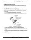
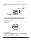
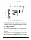
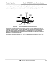
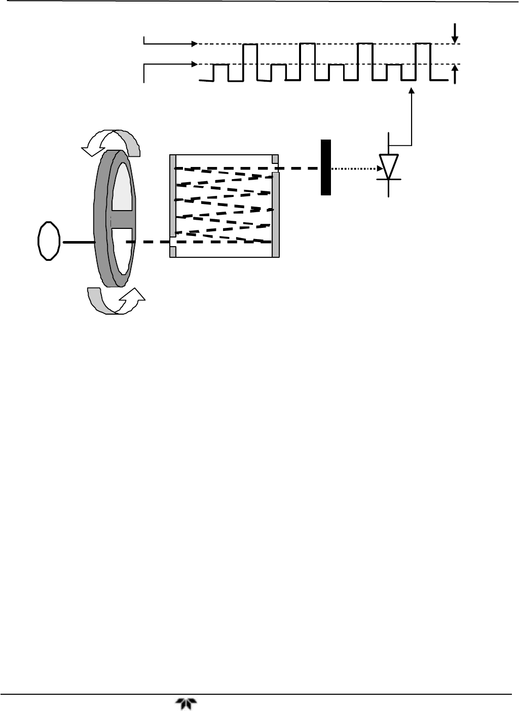
Figure 9-3: Measurement Fundamentals with GFC Wheel
As the GFC wheel spins, the IR light alternately passes through the two cavities. When the beam is
exposed to the reference cell, the CO
2
in the gas filter wheel strips the beam of most of the IR at 4.3μm.
When the light beam is exposed to the measurement cell, the N
2
in the filter wheel does not absorb IR
light. This results in a fluctuation in the intensity of the IR light striking the photo-detector (See Figure 10-
3) that results in the output of the detector resembling a square wave.
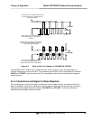
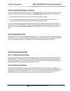
9.1.3.2. The Measure Reference Ratio
The Model GFC 7000TA determines the amount of CO
2
in the sample chamber by computing the ratio
between the peak of the measurement pulse (CO2 MEAS) and the peak of the reference pulse (CO2
REF).
If no gases exist in the sample chamber that absorb light at 4.3μm, the high concentration of CO
2
in the
gas mixture of the reference cell will attenuate the intensity of the IR beam by 60% giving a M/R ratio of
approximately 2.4:1.
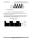
Adding CO
2
to the sample chamber causes the peaks corresponding to both cells to be attenuated by a
further percentage. Since the intensity of the light passing through the measurement cell is greater, the
effect of this additional attenuation is greater. This causes CO2 MEAS to be more sensitive to the
presence of CO
2
in the sample chamber than CO2 REF and the ratio between them (M/R) to move closer
to 1:1 as the concentration of CO
2
in the sample chamber increases.