Operating Instructions Model GFC7000TA Carbon Dioxide Analyzer
Teledyne Analytical Instruments 123
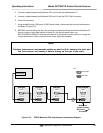
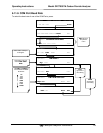
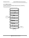
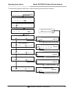
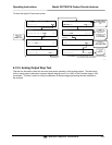
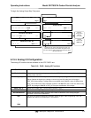
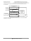
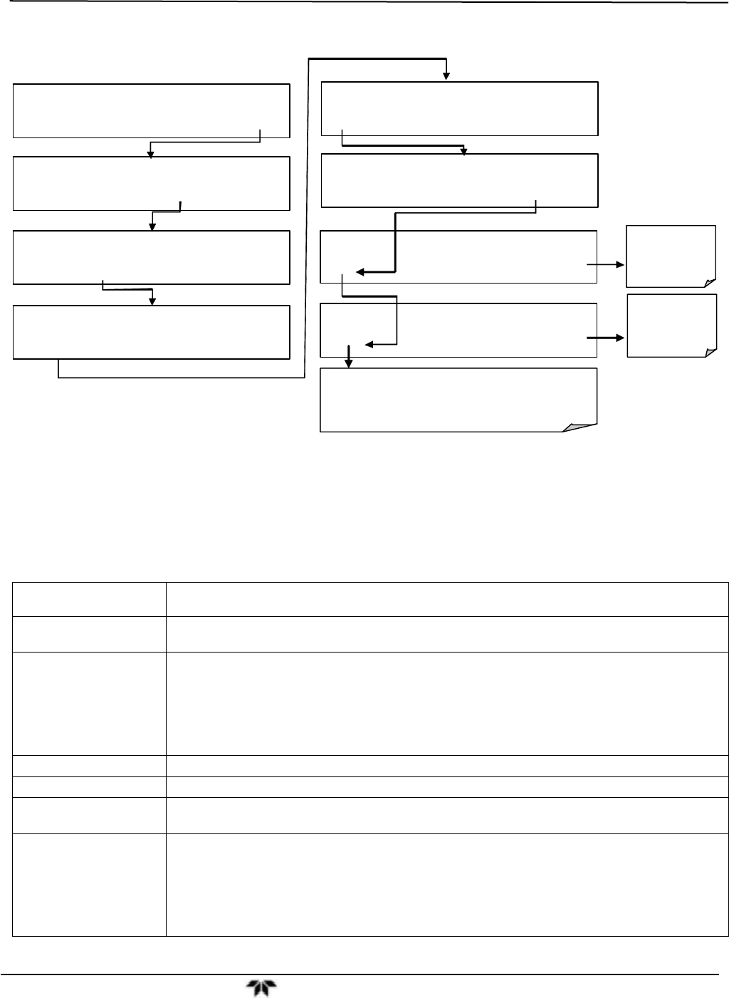
To begin the Analog Output Step Test press:
SETUP X.X SECONDARY SETUP MENU
COMM VARS DIAG ALRM EXIT
SAMPLE RANGE = 500.000 PPM CO2 =X.XXX
< TST TST > CAL SETUP
SETUP X.X PRIMARY SETUP MENU
CFG DAS RNGE PASS CLK MORE EXIT
DIAG SIGNAL I / O
NEXT ENTR EXIT
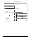
Exit-Exit
returns to the
DIAG menu
DIAG
A
NALOG OUTPUT
PREV NEXT ENTR EXIT
DIAG AOUT ANALOG OUTPUT
0% EXIT
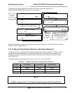
Performs
analog output
step test.
0% - 100%
DIAG AOUT ANALOG OUTPUT
[0%] EXIT
Pressing the “0%” button while performing the test will
pause the test at that level. Brackets will appear around
the value: example: [20%] Pressing the same button again
will resume the test.
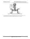
SETUP X.X ENTER DIAG PASS: 818
8 1 8 ENTR EXIT
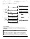
6.13.4. Analog I/O Configuration
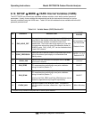
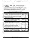
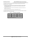
The analog I/O functions that are available in the GFC 7000TA are:
Table 6-16: DIAG - Analog I/O Functions
Sub Menu Function
AOUTS CALIBRATED: Shows the status of the analog output calibration (YES/NO) and initiates a calibration of all
analog output channels.
CONC_OUT_1
Sets the basic electronic configuration of the A1 analog output (CO
2
). There are three options:
Range: Selects the signal type (voltage or current loop) and full scale level of the output.
REC_OFS: Allows setting a voltage offset (not available when RANGE is set to CURRent loop.
Auto_CAL: Performs the same calibration as AOUT CALIBRATED, but on this one channel only.
NOTE: Any change to RANGE or REC_OFS requires recalibration of this output.
CONC_OUT_2
Same as for CONC_OUT_1 but for analog channel 2 (CO
2
)
TEST OUTPUT
Same as for CONC_OUT_1 but for analog channel 4 (TEST)
AIN CALIBRATED Shows the calibration status (YES/NO) and initiates a calibration of the analog to digital
converter circuit on the motherboard.
XIN1
.
.
.
XIN8
For each of 8 external analog input channels, shows the gain, offset, engineering units, and
whether the channel is to show up as a Test function.


