


Troubleshooting Model GFC7000TA Carbon Dioxide Analyzer
Teledyne Analytical Instruments 241
10.5. Subsystem Checkout
The preceding s of this manual discussed a variety of methods for identifying possible sources of failures
or performance problems within the analyzer. In most cases this included a list of possible causes. This
describes how to determine individually determine if a certain component or subsystem is actually the
cause of the problem being investigated.
10.5.1. AC Mains Configuration
The analyzer is correctly configured for the AC mains voltage in use if:
1. The Sample Pump is running.
2. The GFC wheel motor is spinning. LED’s D1 & D2 (located on the synch/demod PCA) should be
flashing.
3. If incorrect power is suspected, check that the correct voltage and frequency is present at the line
input on the rear panel.
If the unit is set for 230 VAC and is plugged into 115VAC, or 100VAC the sample pump
will not start, and the heaters will not come up to temperature.
If the unit is set for 115 or 100 VAC and is plugged into a 230 VAC circuit, the circuit
breaker built into the ON/OFF Switch on the Front Panel will trip to the OFF position
immediately after power is switched on.
10.5.2. DC Power Supply
If you have determined that the analyzer’s AC mains power is working, but the unit is still not operating
properly, there may be a problem with one of the instrument’s switching power supplies. The supplies
can have two faults, namely no DC output, and noisy output.
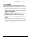
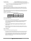
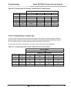
To assist tracing DC Power Supply problems, the wiring used to connect the various printed circuit
assemblies and DC Powered components and the associated test points on the relay board follow a
standard color-coding scheme as defined in the following table.
Table 10-6: DC Power Test Point and Wiring Color Codes
NAME TEST POINT# TP AND WIRE COLOR
Dgnd
1
Black
+5V
2
Red
Agnd
3
Green
+15V
4
Blue
-15V
5
Yellow
+12R
6
Purple
+12V
7
Orange