


Getting Started Model GFC7000TA Carbon Dioxide Analyzer
Teledyne Analytical Instruments 23
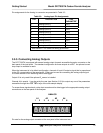
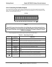
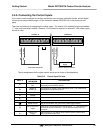
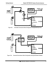
3.5.4. Connecting the Status Outputs
If you wish utilize the analyzer’s status outputs to interface with a device that accepts logic-level digital
inputs, such as programmable logic controllers (PLC’s) they are accessed via a 12-pin connector on the
analyzer’s rear panel labeled STATUS.
STATUS
1 2 3 4 5 6 7 8 D
+
NOTE
Most PLC’s have internal provisions for limiting the current the input will draw.
When connecting to a unit that does not have this feature, external resistors must
be used to limit the current through the individual transistor outputs to ≤50mA
(120 Ω for 5V supply).
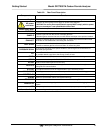
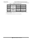
The pin assignments for the status outputs can be found in the table below:
Table 3-5: Status Output Pin-outs
OUTPUT #
STATUS
DEFINITION
CONDITION
1
SYSTEM OK
On if no faults are present.
2
CONC VALID
On if CO
2
concentration measurement is valid.
If the CO
2
concentration measurement is invalid, this bit is OFF.
3
HIGH RANGE
On if unit is in high range of DUAL or AUTO range modes.
4
ZERO CAL
On whenever the instruments ZERO point is being calibrated.
5
SPAN CAL
On whenever the instruments SPAN point is being calibrated.
6
DIAG MODE
On whenever the instrument is in DIAGNOSTIC mode.
7
ALARM1
On whenever the measured CO
2
concentration is above the set point for
ALM1
8
ALARM2
On whenever the measured CO
2
concentration is above the set point for
ALM2
D EMITTER BUS The emitters of the transistors on pins 1-8 are bused together.
+ DC POWER + 5 VDC
Digital Ground The ground level from the analyzer’s internal DC power supplies.