Table of Contents Model GFC7000TA Carbon Dioxide Analyzer
Teledyne Analytical Instruments xi
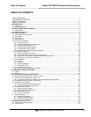
TABLE OF CONTENTS
SAFETY MESSAGES ............................................................................................................................................... v
CONSIGNES DE SÉCURITÉ ................................................................................................................................... vi
ABOUT this MANUAL .............................................................................................................................................. ix
TABLE OF CONTENTS ........................................................................................................................................... xi
1. INTRODUCTION ........................................................................................................................................................ 1
1.1. Features ............................................................................................................................................................. 1
1.2. Using This Manual .............................................................................................................................................. 1
2. SPECIFICATIONS AND APPROVALS ..................................................................................................................... 5
2.1. Specifications ..................................................................................................................................................... 5
2.2. CE Mark Compliance ......................................................................................................................................... 7
3. GETTING STARTED ................................................................................................................................................. 9
3.1. Unpacking and Initial Set Up .............................................................................................................................. 9
3.2. Front Panel ....................................................................................................................................................... 11
3.3. Rear Panel ....................................................................................................................................................... 15
3.4. Internal Layout ................................................................................................................................................. 17
3.5. Electrical Connections ...................................................................................................................................... 19
3.5.1. Power Connection .................................................................................................................................... 20
3.5.2. Connecting Analog Inputs (Option 64) ...................................................................................................... 20
3.5.3. Connecting Analog Outputs ...................................................................................................................... 21
3.5.4. Connecting the Status Outputs ................................................................................................................. 23
3.5.5. Connecting the Control Inputs .................................................................................................................. 24
3.5.6. Connecting the Communications Interfaces ............................................................................................. 25
3.6. Pneumatic Connections ................................................................................................................................... 25
3.6.1. Basic Pneumatic Connections .................................................................................................................. 26
3.6.2. Connections with Internal Valve Options Installed .................................................................................... 30
3.6.3. Pneumatic Connections in Multipoint Calibration Applications.................................................................. 32
3.6.4. Setting the Internal Purge Air Pressure .................................................................................................... 32
3.7. Initial Operation ................................................................................................................................................ 33
3.7.1. Startup ...................................................................................................................................................... 33
3.7.2. Warm Up................................................................................................................................................... 34
3.7.3. Warning Messages ................................................................................................................................... 34
3.7.4. Functional Check ...................................................................................................................................... 36
3.8. Initial Calibration Procedure ............................................................................................................................. 37
3.8.1. Initial O
2
Sensor Calibration Procedure .................................................................................................... 40
4. FREQUENTLY ASKED QUESTIONS ..................................................................................................................... 45
4.1. FAQ’s ............................................................................................................................................................... 45
4.2. Glossary ........................................................................................................................................................... 46
5. OPTIONAL HARDWARE AND SOFTWARE .......................................................................................................... 51
5.1. Rack Mount Kits (Options 20A, 20B, 21 and 23) .............................................................................................. 51
5.2. Current Loop Analog Outputs (Option 41) ........................................................................................................ 51
5.2.1. Converting Current Loop Analog Outputs to Standard Voltage Outputs ................................................... 52
5.3. Expendable Kits (Options 42C, 42D and 43) .................................................................................................... 53
5.4. Calibration Valves Options ............................................................................................................................... 54
5.4.1. Ambient Zero/Pressurized Span Valve ..................................................................................................... 54
5.4.2. Ambient Zero/Ambient Span Valve ........................................................................................................... 55
5.5. Communication Options ................................................................................................................................... 57
5.5.1. Communications Cables ........................................................................................................................... 57
5.5.2. RS-232 Multidrop (Option 62) ................................................................................................................... 57
5.6. Oxygen Sensor (OPT 65) ................................................................................................................................. 58
5.6.1. Theory of Operation .................................................................................................................................. 58
5.7. Special Features .............................................................................................................................................. 61
5.7.1. Dilution Ratio Option ................................................................................................................................. 61
5.7.2. Maintenance Mode Switch ........................................................................................................................ 61
5.7.3. Second Language Switch ......................................................................................................................... 61
6. OPERATING INSTRUCTIONS ................................................................................................................................ 63
6.1. Overview of Operating modes .......................................................................................................................... 63
6.2. Sample Mode ................................................................................................................................................... 64


