


Operating Instructions Model GFC7000TA Carbon Dioxide Analyzer
Teledyne Analytical Instruments 142
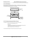
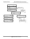
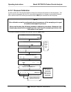
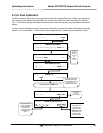
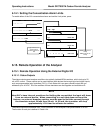
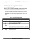
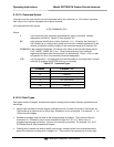
6.14.1. Setting the Concentration Alarm Limits
To enable either of the CO
2
concentration alarms and set the Limit points, press:
ENT
R
accepts the new
settings
EXIT ignores the new
settings
SETUP X.
A
LARM 1 LIMIT: 200.00 PPM
0 1 0 0 .0 0 ENTR EXIT
SETUP X.X
A
LARM MENU
ALM1 ALM2 EXIT
SETUP X.
A
LARM 1 LIMIT: OFF
OFF ENTR EXIT
SETUP X.X
PRIMARY SETUP MENU
CFG DAS RNGE PASS CLK MORE EXIT
SETUP X.X SECONDARY SETUP MENU
COMM VARS DIAG ALRM EXIT
SAMPLE* RANGE = 500.000 PPM CO2 =X.XXX
< TST TST > CAL SETUP
Toggle these buttons to
scroll through the
available character set:
0-9
SETUP X.
A
LARM 1 LIMIT: ON
ON ENTR EXIT
6.15. Remote Operation of the Analyzer
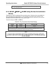
6.15.1. Remote Operation Using the External Digital I/O
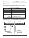
6.15.1.1. Status Outputs
The status outputs report analyzer conditions via optically isolated NPN transistors, which sink up to 50
mA of DC current. These outputs can be used interface with devices that accept logic-level digital inputs,
such as programmable logic controllers (PLC’s). Each Status bit is an open collector output that can
withstand up to 40 VDC. All of the emitters of these transistors are tied together and available at D.
NOTE
Most PLC’s have internal provisions for limiting the current that the input will draw
from an external device. When connecting to a unit that does not have this
feature, an external dropping resistor must be used to limit the current through
the transistor output to less than 50 mA. At 50 mA, the transistor will drop
approximately 1.2V from its collector to emitter.
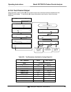
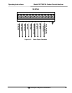
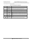
The status outputs are accessed via a 12-pin connector on the analyzer’s rear panel labeled STATUS.
The function of each pin is defined in Table 6–24.