


Getting Started Model GFC7000TA Carbon Dioxide Analyzer
Teledyne Analytical Instruments 24
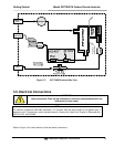
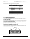
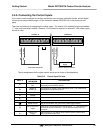
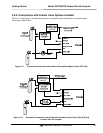
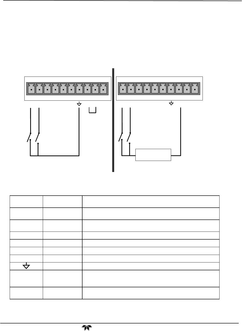
3.5.5. Connecting the Control Inputs
If you wish to use the analyzer to remotely activate the zero and span calibration modes, several digital
control inputs are provided through a 10-pin connector labeled CONTROL IN on the analyzer’s rear
panel.
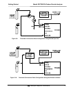
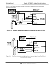
There are two methods for energizing the control inputs. The internal +5V available from the pin labeled
“+” is the most convenient method. However, if full isolation is required, an external 5 VDC power supply
should be used.
CONTROL IN
A B C D E F U +
S
P
A
N
Z
E
R
O
CONTROL IN
A B C D E F U +
-
+
5 VDC Power
Supply
S
P
A
N
Z
E
R
O
Local Power Connections
External Power Connections
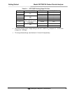
The pin assignments for the digital control inputs can be found in the table below:
Table 3-6: Control Input Pin-outs
INPUT #
STATUS
DEFINITION
ON CONDITION
A
REMOTE ZERO
CAL
The Analyzer is placed in Zero Calibration mode. The mode field of
the display will read ZERO CAL R.
B
REMOTE
SPAN CAL
The Analyzer is placed in Span Calibration mode. The mode field of
the display will read SPAN CAL R.
C
SPARE
D
SPARE
E
SPARE
F
SPARE
Digital Ground May be connected to the ground of the data logger/recorder.
U
Pull-up supply for
inputs
Input pin for +5 VDC required to activate pins A – F. This can be from
an external source or from the “+” pin of the instruments STATUS
connector.
+
Internal +5V
Supply
Internal source of +5V which can be used to actuate control inputs
when connected to the U pin.