


Pelco Manual C543M-A (7/03) 47
6.0 PROGRAMMING NOTES–ODDS AND ENDS
The following programming notes are brief and are put here only as an indication of
the areas of programming that affect the matrix bay or as a “memory check” for
those already familiar with programming. The following should not be used as a
substitute for the programming manual itself, which should be consulted whenever
any programming changes or additions of substance are made.
Video Loss
Alarm and video modes of Video loss will not be activated unless the fourth switch
position of the S2 switch on the Output card for the matrix bay in which the associated
camera is located is set to ON. It is-by default-in the OFF position.
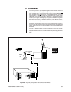
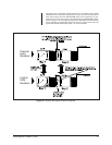
Video Matrix Bay Numbering (Sideframing)
The Current operating software allows sideframing, of up to eight additonal matrix
bays besides the first, making the total available input capacity of sideframed matrix
bays, 2048. This input capacity increases via the networking of multiple systems.
When programming the COMMS Setup dialog box (.SCP file) as part of programming
your configuration files, there is an entry field for Equipment numbers to be entered
for all devices tied to SerCom ports on the CM9760-CC1. The matrix bay is no
exception; therefore, each matrix bay used in a system must be attached to a com-
munication port on the CC1. Whenever only “one” video matrix bay is attached to a
CC1, you must assign an equipment number of 2 to the port where it’s connected.
If another bay is attached to a different port on the CC1 and is the first sideframed
bay, the port where its connected is assigned an equipment number of 12 in the
equipment field. Likewise, a second and third sideframing bay are assigned Equip-
ment Numbers of 22 and 32, respectively.
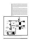
Adding a Video Matrix Bay Directly to an Existing System
The following is a quick reference for using 9760 Configuration Setup files to add a
matrix bay to a 9760 System.
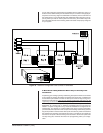
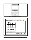
1. Click on the Setup icon on the toolbar so that the Configuration files dialog box
appears on the screen (refer to Figure 37).
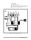
2. Select the node you wish to edit.
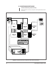
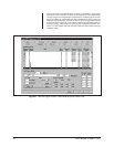
3. Click on “Setup Files” and the Setup File dialog box should appear on screen;
select COMMS (refer to Figure 38).
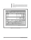
4. In the Comms Setup dialog box that appears on screen, type the appropriate
Equipment number in the Equipment Number Box (in our example, we entered
the number 2), depending on what you plan to do with the matrix bay (i.e.,
downframe, sideframe).
5. Type in the baud rate and parity.
6. Enter any descriptive information you wish and click on Save.
7. Make sure directly and indirectly associated setup file Dialog boxes are also
configured to reflect the changes made. In most cases these would be Camera