


Pelco Manual C543M-A (7/03) 23
What Are Its Functions?
The Video Input Card also handles several functions:
1. The card accepts up to 16 video input signals from the Rear Panel BNC Card
and switches them to the 16 lines of the video output bus.
2. Accepts and acts upon control data coming from the Video Output Card.
3. Synchronizes matrix switching with the vertical interval and reports card status.
4. Acts as a power-up configuration watchdog and monitors serial communica-
tions with the output card controller and causes the COMMS failure LED to
light as a result of any conditions that can cause a communication failure.
5. Monitors Video Loss and raises a video fail flag in the case of signal loss and
notifies the Output Card Controller.
Other Important Items
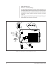
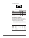
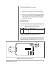
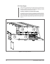
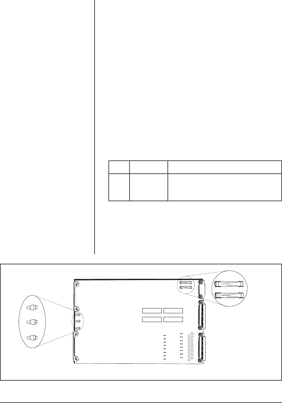
Video Input Card LEDs
Each of the 16 possible Video Input Cards is equipped with three LEDs labeled
CR1, CR2, and CR3. Refer to Table F for a complete description of the Video Input
Card LEDs. Further information regarding LED diagnostics is found in Section 3.4.
Table F. Video Input Card LED Assignments
LED COLOR WHEN LED IS ON
CR1 Red Communications failure with the CM9760-CC1
CR2 Green +10 VDC is OK
CR3 Green –10 VDC is OK
The Video Input Card has no jumper or switch settings to worry about.
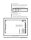
Video Input Card Fusing
Two power fuses, F1 and F2 exist on each Video Input Card. Refer to Figure 15 for
fuse locations. Both of the front panel LEDs should be lit at all times (CR2 and
CR3). If one or both are Out on any card, remove the affected card, and check the
fuses. Replace defective fuses and reinstall the card.
Figure 15. Input Card LED and Fusing Locations
CR1 RED
CR2 GREEN
CR3 GREEN
F1
.7ASB
F2
.7ASB